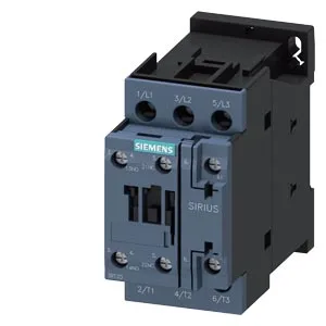
Siemens 3RT2028-1AL20-ZW96 — Contactors

Siemens 3RT2028-1AL20-ZW96 SIRIUS Power Contactor, S0 Frame

MPN3RT2028-1AL20-ZW96
Active

Siemens SIRIUS 3RT2028-1AL20-ZW96 power contactor, S0 frame, 45 mm width, 85 mm height, 97 mm depth, screw and snap-on 35 mm DIN rail mounting, auxiliary switch included.

Sourced new & surplus through independent channelsAuthenticity-screened · ESD-safe packingListing updated Aug 2026

Specifications

3RT2028-1AL20-ZW96 — Identification
ParameterValue
Contactor frame sizeS0
3RT2028-1AL20-ZW96 — Ratings & Performance
ParameterValue
Rated operational current, AC-12, max.10 A
Rated operational current, AC-4 @ 400 V22 A
Rated value @ 400 V3 A
Rated value @ 500 V2 A
Rated value @ 690 V1 A
Rated value @ 230 V5 hp
Rated value @ 24 V10 A
Rated value @ 60 V2 A
Rated value @ 110 V1 A
Rated value @ 220 V0.3 A
3RT2028-1AL20-ZW96 — Control & Coil
ParameterValue
Control supply voltage typeAC
Rated value @ 50 Hz0.25
Rated value @ 50 Hz230 V
3RT2028-1AL20-ZW96 — Contacts & Poles
ParameterValue
Main poles3
Main NO contacts3
Auxiliary contact reliability1 faulty switching per 100 million (17 V, 1 mA)
3RT2028-1AL20-ZW96 — Protection & Coordination
ParameterValue
Short-circuit coordination type 1, fusegG: 125A (690V,100kA), aM: 50A (690V,100kA), BS88: 125A (415V,80kA)
Short-circuit coordination type 2, fusegG: 50A (690V,100kA), aM: 25A (690V, 100kA), BS88: 50A (415V, 80kA)
Aux. switch short-circuit protection, fusegG: 10 A (500 V, 1 kA)
3RT2028-1AL20-ZW96 — Connection & Mounting
ParameterValue
Main circuit connectionscrew-type terminals
Aux. / control circuit connectionscrew-type terminals
Conductor cross-section, solid1 ... 10 mm²
Conductor cross-section, solid or stranded2x (0.5 ... 1.5 mm²), 2x (0.75 ... 2.5 mm²)
Conductor cross-section, finely stranded w/ ferrule2x (0.5 ... 1.5 mm²), 2x (0.75 ... 2.5 mm²)
Mounting methodscrew and snap-on mounting onto 35 mm DIN rail according to DIN EN 60715
Side-by-side mountingYes
3RT2028-1AL20-ZW96 — Durability
ParameterValue
Durability (operating cycles, typ.)10 000 000
Durability with aux. switch block (cycles, typ.)10 000 000
3RT2028-1AL20-ZW96 — Environmental
ParameterValue
Operating temperature range-25 ... +60 °C
Storage temperature range-55 ... +80 °C
Installation altitude, max.2 000 m
3RT2028-1AL20-ZW96 — Mechanical
ParameterValue
Width45 mm
Height85 mm
Depth97 mm
3RT2028-1AL20-ZW96 — Specifications
ParameterValue
At AC4 ... 16 ms

Product details

S0 frame, 45 mm wide — panel fit constraints

The 3RT2028-1AL20-ZW96: That 45 mm width is the critical dimension for DIN-rail density — it occupies a single 45 mm module on the rail, so a 600 mm rail section holds 13 units with no gap. These are the minimum air gaps to maintain rated insulation — tighter spacing risks flashover between phases or to ground.

Wire termination — main and auxiliary contacts

The magnet coil uses screw-type terminals — no push-in or spring-cage option on this variant, so factor in screwdriver access during panel wiring.

Rated for 10 million mechanical operations typical — that's the contactor body itself, not the contacts under load. For a line running 10 cycles per hour, that's over 100 years of mechanical life; the electrical endurance under load is the real limit. Maximum switching frequency depends on duty class: 1000 operations per hour in AC-1 (resistive loads), 750 ops/h in AC-2, AC-3, and AC-3e (motor starting/running), and 250 ops/h in AC-4 (plugging, inching, reversing). Exceeding these rates shortens contact life — the arcing time of 4 to 16 ms per operation adds up fast at high cycle rates.

Auxiliary contact ratings — what they switch

At 400 V it's rated 3 A. These are the make/break capacities for the control circuit — don't assume the 10 A rating holds at higher voltages. Breaking capacity at 50 Hz is 0.25 A, at 60 Hz is 0.28 A — these are the maximum currents the auxiliary contacts can interrupt in an AC control circuit. For DC control, use the voltage-specific ratings above.

MPN
3RT2028-1AL20-ZW96