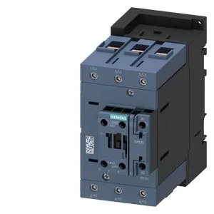
Siemens 3RT2047-1XB40-0LA2 — Contactors

Siemens 3RT2047-1XB40-0LA2 SIRIUS Contactor, 24 VDC, 96 A at

MPN3RT2047-1XB40-0LA2
Active

Siemens SIRIUS, S3 frame contactor, 3RT2047-1XB40-0LA2, 24 V DC coil, screw-type terminals, 96 A at 480 V AC, 99 A at 600 V AC, auxiliary switch included, screw and snap-on DIN rail mounting.

Sourced new & surplus through independent channelsAuthenticity-screened · ESD-safe packingListing updated Aug 2026

Specifications

3RT2047-1XB40-0LA2 — Identification
ParameterValue
Contactor frame sizeS3
3RT2047-1XB40-0LA2 — Ratings & Performance
ParameterValue
Rated operational current, AC-12, max.10 A
Rated operational current, AC-4 @ 400 V97 A
Rated value @ 400 V3 A
Rated value @ 500 V2 A
Rated value @ 690 V1 A
Rated value @ 230 V20 hp
Rated value @ 24 V10 A
Rated value @ 60 V2 A
Rated value @ 110 V1 A
Rated value @ 220 V0.3 A
3RT2047-1XB40-0LA2 — Control & Coil
ParameterValue
Control supply voltage typeDC
3RT2047-1XB40-0LA2 — Contacts & Poles
ParameterValue
Main poles3
Main NO contacts3
3RT2047-1XB40-0LA2 — Protection & Coordination
ParameterValue
Short-circuit coordination type 1, fusegG: 250 A (690 V, 100 kA), aM: 160 A (690 V, 100 kA), BS88: 200 A (415 V, 80 kA)
Short-circuit coordination type 2, fusegG: 200A (690V,100kA), aM: 100A (690V,100kA), BS88: 160A (415V,80kA)
Aux. switch short-circuit protection, fusegG: 10 A (500 V, 1 kA)
3RT2047-1XB40-0LA2 — Connection & Mounting
ParameterValue
Main circuit connectionscrew-type terminals
Aux. / control circuit connectionscrew-type terminals
Conductor cross-section, solid or stranded2x (0.5 ... 1.5 mm²), 2x (0.75 ... 2.5 mm²)
Conductor cross-section, finely stranded w/ ferrule2x (0.5 ... 1.5 mm²), 2x (0.75 ... 2.5 mm²)
Mounting methodscrew and snap-on mounting onto 35 mm standard mounting rail according to DIN EN 60715
Side-by-side mountingYes
3RT2047-1XB40-0LA2 — Durability
ParameterValue
Durability (operating cycles, typ.)10 000 000
Durability with aux. switch block (cycles, typ.)10 000 000
3RT2047-1XB40-0LA2 — Environmental
ParameterValue
Operating temperature range-40 ... +70 °C
Storage temperature range-55 ... +80 °C
Installation altitude, max.2 000 m
3RT2047-1XB40-0LA2 — Mechanical
ParameterValue
Width70 mm
Height140 mm
Depth152 mm

Product details

The main contacts carry 96 A at 480 V and 99 A at 600 V, which means it handles moderate-to-high current motor circuits in North American 480 V or 600 V distribution systems without requiring an external contactor upgrade. The auxiliary contact switching capacity is specified per DC voltage: 10 A at 24 V, 2 A at 48 V, 2 A at 60 V, 1 A at 110 V, 0.9 A at 125 V, 0.3 A at 220 V, 3 A at 400 V, 2 A at 500 V, and 1 A at 690 V. These are the DC-13 ratings for the auxiliary circuit — useful for pilot duty or PLC interposing relays where the load is inductive.

The contactor occupies a 70 mm width, 140 mm height, and 152 mm depth envelope. These are the minimum air gaps to adjacent metal or grounded surfaces for safe arc quenching. The coil connection uses screw-type terminals accepting 2x (0.5 to 1.5 mm²) or 2x (0.75 to 2.5 mm²) solid or stranded wire. The main contact terminals follow the same wire range.

Performance and environmental limits

The coil draws a 6.5 A inrush peak at 24 V DC. The dropout voltage is 0.7 times the rated value. The arcing time for the main contacts is 10 to 20 ms, and the DC operating time (coil pickup to main contact closure) is 38 to 57 ms. The maximum switching frequency at AC-4 duty (severe motor starting) is 200 operations per hour.

Frequently asked questions

What is the mounting footprint of this contactor?

The envelope is 70 mm wide, 140 mm high, and 152 mm deep. It mounts on a 35 mm DIN rail per DIN EN 60715 with screw or snap-on fastening. Minimum clearance is 10 mm upward, 20 mm forward, 10 mm downward, and 10 mm at the side.

MPN
3RT2047-1XB40-0LA2