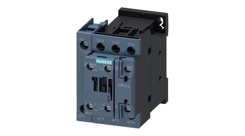
It mounts by screw or snap-on onto 35 mm DIN rail per DIN EN 60715, and the mounting position allows ±180° rotation on a vertical surface plus ±22.5° forward/backward tilt — useful when panel layout forces an unconventional orientation. The coil draws a 3 A inrush peak and holds at 10 A at the 24 V rated value. Drop-out timing across the DC coil measures 30 to 50 ms, and the arcing time sits at 10 ms. These numbers matter for control logic sequencing — the dropout delay is long enough that a downstream PLC input seeing the auxiliary contact may need a debounce filter if the contactor is used in a fast-cycle application. The operating range covers most indoor industrial enclosures without forced cooling.
Auxiliary circuits take 0.5 to 2.5 mm² solid or stranded (2x per terminal). The spring-cage design eliminates periodic re-torquing common with screw terminals on high-vibration installations like conveyor drives or compressor skids. Clearance distances: 10 mm upward, forward, and downward; 6 mm at the side. The S0 frame measures 60 mm wide by 102 mm high by 107 mm deep — confirm these against your existing panel cutout or DIN-rail end-stop clearance before ordering.
Switching capacity and duty cycles
Maximum mechanical switching rate: 750 operations per hour under AC-1, AC-2, and AC-3 duty; 250 per hour under AC-4. The AC-4 rate is the limiting factor for plugging or inching applications — if your cycle profile includes frequent reversing or jogging, derate accordingly. Rated operational current at 24 VDC is 10 A; at 48 VDC and 60 VDC it drops to 2 A; at 110 VDC it is 1 A; at 125 VDC it is 0.9 A; at 220 VDC it is 0.3 A. The DC switching capacity follows the expected inverse relationship with voltage — verify your load's DC voltage and current against these points, not just the AC rating.