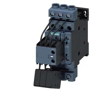
Capacitor switching — what the making and breaking ratings mean
The 3RT2627-1AP65: This is a SIRIUS capacitor contactor, size S0, designed specifically for switching capacitor banks in power factor correction (PFC) panels. The distinction from a standard motor contactor matters: capacitor inrush current can exceed steady-state by 20–50x, so the contactor must make the circuit before the pre-charge resistors drop out and break it without welding the main poles. Arcing time is 10 ms typical, with a total make/break time of 4–16 ms AC. The maximum switching rate is 100 operations per hour at 230–600 V, dropping to 72/h at 690 V — this sets the upper bound for how often the PFC controller can step the bank in and out.
Coil voltage and termination — 220–240 V AC, screw terminals
The magnet coil is rated 220 V at 50 Hz and 240 V at 60 Hz, AC only — no DC coil variant here. The coil termination is screw-type terminals, not spring-cage or push-in, so the kit needs a screwdriver (Pozidriv #2 or flat 0.6×3.5 mm) and a torque driver set to the terminal screw spec. Stranded: 2× (1–2.5 mm²) or 2× (2.5–10 mm²). At 40 °C ambient, one 10 mm² conductor fits; at 60 °C, two 10 mm² conductors fit — the higher temperature derates the current but the terminal capacity increases.
DIN rail mount, S0 frame, 45 mm wide
The S0 frame is 45 mm wide, 135 mm high, 155 mm deep. No auxiliary contact block is attached from the factory (0 attachable blocks listed), so if the BOM calls for a feedback contact, order the matching S0 auxiliary switch separately.
Lifecycle and sourcing — active production, quoted per BOM
For a PFC panel build or MRO spare, the kit is complete: the contactor ships with the coil, main poles, and mounting hardware — no hidden accessory pack needed.