Key ratings and what they mean for your circuit
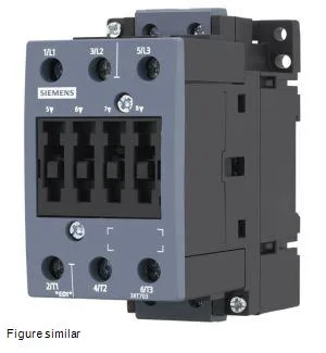
The 3RT7036-1AG20: Three main poles handle the load circuit; the contactor is rated for AC-3 duty up to 690 V, which covers most 400 V and 690 V motor applications in industrial panels. The auxiliary contact block supports a 230 V rated current of 6 A, 400 V at 3 A, and 690 V at 1 A — these are the switching limits for control or signaling circuits, not the main motor path. The auxiliary contacts are rated for PLC-level reliability (17 V, 5 mA), so they can drive a digital input directly without a separate interface relay.
Mechanical integration and mounting
Mounts via screw or snap-on onto a 35 mm DIN rail per DIN EN 50022. The mounting position is flexible: ±180° rotation on a vertical surface, and can be tilted forward/backward by ±22.5°. Side-by-side mounting is permitted, so multiple contactors can pack tightly on the rail without mandatory spacing. Dimensions are 115 mm deep, 55 mm wide, 112 mm high — the S2 frame size keeps the footprint compact for a 3-pole contactor in this current class.
Coil and control supply
The control supply voltage is AC only — 110 V at both 50 Hz and 60 Hz. Coil draw is 0.36 A at 50 Hz and 0.38 A at 60 Hz. Closing power is 0.76 W DC; holding power drops to 0.35 W DC, which means the coil driver sees a brief inrush then a lower steady-state load. The surge voltage resistance is 6 kV, adequate for industrial environments with moderate transient exposure.
Switching frequency and environmental limits
Maximum switching rate is 800 operations per hour under AC-3 duty and 250 per hour under AC-4 duty — AC-4 (plugging/inching) generates more arc wear, so the lower limit is the one to respect for frequent reversing or jogging applications. Operating temperature range is -10 to +55 °C; storage range is -25 to +70 °C. Pollution degree 3 means it is suited for industrial atmospheres with conductive dust or humidity, typical for an enclosed panel.
Short-circuit coordination and wiring
For type 2 coordination (no damage to the contactor after a short-circuit), the required upstream fuse is a gL/gG NH 3NA 80 A. For type 1 coordination (contactor may need replacement after fault), the fuse is 160 A. These are the fuse sizes to specify when designing the branch circuit. Terminal wiring accepts 2x (0.5 to 1.5 mm²) or 2x (0.75 to 2.5 mm²) solid or stranded, and finely stranded with ferrules — covers standard panel wire sizes.