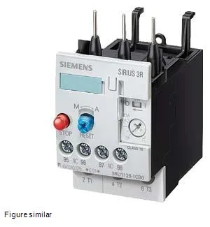
The ATEX approval (DMT 98 ATEX G 001) qualifies it for explosive-gas environments — a spec that often gates the BOM in chemical or oil-and-gas panels.
Mounting and Integration Constraints
The relay mounts stand-alone (no DIN-rail adapter required) on a vertical surface, with ±135° rotation and ±45° tilt front-to-back — useful when gland-plate access or cable routing forces an off-axis panel layout. That zero-clearance top and bottom means you can stack it tight against other S0 devices without derating for airflow, but the 6 mm side gap must be respected to avoid heat buildup from adjacent power components. Dimensions: 45 mm wide, 97 mm high, 96 mm deep — the depth is the key envelope check for shallow enclosures.
Solid conductors: 2x (0.5–2.5 mm²) for both main and aux circuits; finely stranded with core-end processing: 2x (0.5–1.5 mm²). For AWG aux cables: 2x (20–14). The Cage Clamp on the aux side is a time-saver in high-density panels — no screw torque to verify, just insert and lock. Verify the ferrule size if using stranded wire on the aux side; the 1.5 mm² upper bound is the limit.
Auxiliary contact ratings: 1 A at 24 V, 3 A at 120 V, 2 A at 230 V, 1 A at 400 V — these are the switching capacities for the N/O and N/C contacts used in the control circuit. The 3 A at 120 V is the highest figure; if your PLC input card draws more than that, you need an interposing relay. Surge voltage resistance: 6 kV (impulse withstand), which aligns with IEC 60947-1 for industrial environments. Operating temperature: –20 to +70 °C; storage/transport: –55 to +80 °C. 100 % relative humidity during operation — no derating for condensation, but the IP20 front protection means the relay itself is not sealed; it relies on the enclosure.