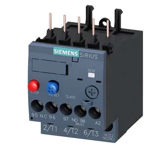
Siemens 3RU2116-1BB0-ZX95 — Overload Relays

Siemens 3RU2116-1BB0-ZX95 SIRIUS Thermal Overload Relay, Siz

MPN3RU2116-1BB0-ZX95
Active

Siemens SIRIUS 3RU2116-1BB0-ZX95 thermal overload relay, size S00, Trip Class 10, contactor mounting, 690 V rated, auxiliary contacts rated 2 A at 24 V.

Source DocumentedChannel stated on listing & quote
Condition PhotosReal unit photos / video on request
WhatsApp AnswersFast human replies for machine-down parts
Worldwide DispatchDHL/FedEx — transit quoted per order
Independent China distributor & sourcing agent· Listing updated Sep 2026

Specifications

3RU2116-1BB0-ZX95 — Identification
ParameterValue
Product brand nameSIRIUS
Product designationthermal overload relay
Frame size (overload relay)S00
Combinable contactor sizesS00
Reference code (IEC 81346-2)F
3RU2116-1BB0-ZX95 — Protection & Trip
ParameterValue
Overload current setting range1.4 ... 2 A
Trip classCLASS 10
Overload release typethermal
3RU2116-1BB0-ZX95 — Electrical (main circuit)
ParameterValue
Rated operational current2 A
Poles (main circuit)3
Rated operating frequency50 ... 60 Hz
Rated insulation voltage (AC, pollution degree 3)690 V
Rated value (AC-3e), max.690 V
Rated surge withstand voltage6 kV
Main current circuitscrew-type terminals
Power loss at rated current (hot)5.7 W
Per pole1.9 W
3RU2116-1BB0-ZX95 — Auxiliary contacts
ParameterValue
Auxiliary contacts: NO1
Auxiliary contacts: NC1
Auxiliary contacts: CO (changeover)0
Auxiliary switch short-circuit protection (required fuse)fuse gG: 6 A, quick: 10 A
Switching current at 24 V2 A
Switching current at 60 V0.3 A
Switching current at 110 V0.22 A
Switching current at 120 V3 A
Switching current at 125 V0.22 A
Switching current at 220 V0.11 A
Switching current at 230 V2 A
Switching current at 400 V1 A
3RU2116-1BB0-ZX95 — Connection & Mounting
ParameterValue
Mounting / fastening methodContactor mounting
Mounting positionany
Main-circuit connector arrangementTop and bottom
Auxiliary/control circuit connection typescrew-type terminals
Removable aux./control terminalNo
Conductor cross-section: solid or stranded2x (0.5 ... 1.5 mm²), 2x (0.75 ... 2.5 mm²)
Conductor cross-section: finely stranded with ferrule2x (0.5 ... 1.5 mm²), 2x (0.75 ... 2.5 mm²)
Conductor range (AWG), main contacts2x (20 ... 16), 2x (18 ... 14), 2x 12
Conductor range (AWG), auxiliary contacts2x (20 ... 16), 2x (18 ... 14)
3RU2116-1BB0-ZX95 — Environmental
ParameterValue
Operating temperature-40 ... +70 °C
Storage temperature-55 ... +80 °C
Transport temperature-55 ... +80 °C
Relative humidity, operating10 ... 95 %
Max. installation altitude2 000 m
3RU2116-1BB0-ZX95 — Mechanical
ParameterValue
Width45 mm
Height76 mm
Depth70 mm

Product details

It protects motors against overload and phase-loss conditions using a bimetallic thermal element.

The relay is rated for main circuit voltages up to 690 V, covering 400 V, 480 V, 500 V, and 690 V line supplies. At 400 V it is rated for 0.75 kW motor load; at 500 V also 0.75 kW; at 690 V it steps to 1.1 kW. These power ratings assume a standard three-phase induction motor — the relay's thermal element is sized to the motor's full-load current, not the kW directly, so the actual setting range on the dial must match the motor nameplate FLA. The auxiliary contacts are rated for switching: 2 A at 24 V, 3 A at 120 V, 2 A at 230 V, and 1 A at 400 V — these are the signal contacts that feed the 'tripped' indication back to the PLC or annunciator. The note 'for message Tripped' on the listing confirms the auxiliary switch is integrated and wired for that purpose.

Fastening method is contactor mounting — no DIN rail adapter needed if paired with a SIRIUS S00 contactor (e.g., 3RT2 series). Main circuit connections are screw-type terminals accepting 2×(0.5…1.5 mm²) or 2×(0.75…2.5 mm²) solid or stranded wire. The auxiliary switch is integrated, so no separate block is required for the trip signal. Temperature compensation is active from -40 to +60 °C, meaning the trip curve stays accurate across that ambient range — important for outdoor or unheated enclosures.

Frequently asked questions

What does the note 'for message Tripped' mean?

It indicates that the integrated auxiliary switch is wired to signal a 'tripped' condition — typically a normally-open contact that closes when the relay trips, sending a signal to a PLC input or annunciator.

What are the auxiliary contact ratings?

The auxiliary contacts are rated: 2 A at 24 V, 3 A at 120 V, 2 A at 230 V, and 1 A at 400 V. These are switching ratings for the signal circuit, not the motor power circuit.

What compliance documentation is available for this part?

The part has a substance prohibitance date of 10/01/2009, confirming RoHS compliance. Siemens provides full compliance documentation (RoHS, REACH, UL, IEC) through their Industry Mall for this order code.

MPN
3RU2116-1BB0-ZX95