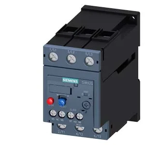
Siemens 3RU2136-4KB1 — Overload Relays

Siemens 3RU2136-4KB1 SIRIUS Thermal Overload Relay, CLASS 10

MPN3RU2136-4KB1
Active

Siemens SIRIUS thermal overload relay, Size S2, CLASS 10A, 690 V rated value, screw-type terminals, for main current circuit.

Source DocumentedChannel stated on listing & quote
Condition PhotosReal unit photos / video on request
WhatsApp AnswersFast human replies for machine-down parts
Worldwide DispatchDHL/FedEx — transit quoted per order
Independent China distributor & sourcing agent· Listing updated Sep 2026

Specifications

3RU2136-4KB1 — Identification
ParameterValue
Product brand nameSIRIUS
Product designationthermal overload relay
Frame size (overload relay)S2
Combinable contactor sizesS2
Reference code (IEC 81346-2)F
3RU2136-4KB1 — Protection & Trip
ParameterValue
Overload current setting range62 ... 73 A
Trip classCLASS 10A
Overload release typethermal
3RU2136-4KB1 — Electrical (main circuit)
ParameterValue
Rated operational current73 A
Poles (main circuit)3
Rated operating frequency50 ... 60 Hz
Rated insulation voltage (AC, pollution degree 3)690 V
Rated value (AC-3e), max.690 V
Rated surge withstand voltage6 kV
Main current circuitscrew-type terminals
Power loss at rated current (hot)17.1 W
Per pole5.7 W
3RU2136-4KB1 — Auxiliary contacts
ParameterValue
Auxiliary contacts: NO1
Auxiliary contacts: NC1
Auxiliary contacts: CO (changeover)0
Auxiliary switch short-circuit protection (required fuse)fuse gG: 6 A, quick: 10 A
Switching current at 24 V2 A
Switching current at 60 V0.3 A
Switching current at 110 V0.22 A
Switching current at 120 V3 A
Switching current at 125 V0.22 A
Switching current at 220 V0.11 A
Switching current at 230 V2 A
Switching current at 400 V1 A
3RU2136-4KB1 — Connection & Mounting
ParameterValue
Mounting / fastening methodstand-alone installation
Mounting positionany
Main-circuit connector arrangementTop and bottom
Auxiliary/control circuit connection typescrew-type terminals
Removable aux./control terminalNo
Conductor cross-section: solid or stranded2x (0.5 ... 1.5 mm²), 2x (0.75 ... 2.5 mm²)
Conductor cross-section: finely stranded with ferrule2x (0.5 ... 1.5 mm²), 2x (0.75 ... 2.5 mm²)
Conductor range (AWG), auxiliary contacts2x (20 ... 16), 2x (18 ... 14)
3RU2136-4KB1 — Environmental
ParameterValue
Operating temperature-40 ... +70 °C
Storage temperature-55 ... +80 °C
Transport temperature-55 ... +80 °C
Relative humidity, operating10 ... 95 %
Max. installation altitude2 000 m
3RU2136-4KB1 — Mechanical
ParameterValue
Width55 mm
Height105 mm
Depth117 mm

Product details

That's fast enough for most standard induction motor starts, but not so fast that it nuisance-trips on a normal acceleration curve. The relay is rated for a maximum insulation voltage of 690 V, and it can handle motor loads up to 55 kW at 690 V or 37 kW at 400 V. The integrated auxiliary switch signals a tripped condition — the note on the part says "for message 'Tripped'" — so the PLC knows exactly why the motor stopped.

Mounting and wiring in the panel

This relay mounts standalone — no DIN rail adapter required, just screw it down. The Size S2 footprint is 105 mm tall, 55 mm wide, and 117 mm deep, so it fits in a standard motor starter cubby. Main circuit connections use screw-type terminals (M6 bolts) and accept 2×(0.5…1.5 mm²) or 2×(0.75…2.5 mm²) solid or stranded wire. The screwdriver shaft needs to be 5–6 mm diameter with a Pozidriv PZ2 tip — keep that in the van. Temperature compensation is active from -40 °C to +60 °C, so the trip curve stays accurate across the operating range.

Auxiliary contact switching capacity

The integrated auxiliary switch can handle a range of control voltages. At 24 V it switches 2 A; at 120 V it handles 3 A; at 230 V it's rated for 2 A; and at 400 V it drops to 1 A. For DC control circuits, it manages 0.3 A at 60 V and 0.22 A at 110 V or 125 V. That covers most PLC input and relay coil loads you'd find in a standard motor control center.

The substance prohibition date is October 15, 2014, which aligns with RoHS compliance requirements. The relay uses a thermal bimetallic overload release — no electronics to fail, just a straightforward mechanical trip that resets manually or automatically depending on the application.

Frequently asked questions

What is the 3RU2136-4KB1 rated for in terms of motor power?

At 400 V it's rated for 37 kW; at 500 V for 45 kW; and at 690 V for 55 kW. The rated insulation voltage is 690 V, and the AC-3e rated voltage maximum is also 690 V.

What does the note 'for message Tripped' mean on this part?

It means the integrated auxiliary switch is wired to send a signal to the control system — typically a PLC input — indicating that the overload relay has tripped. It's not just a visual flag; it's a dry contact that tells the automation system the motor is off due to overload.

What is the depth of the 3RU2136-4KB1?

The depth is 117 mm. Overall dimensions are 105 mm tall by 55 mm wide by 117 mm deep, Size S2.

Where can I buy 3RU2136-4KB1?

This part is sourced to order through independent distribution. Submit an RFQ; we confirm availability and current pricing at quote time.

MPN
3RU2136-4KB1