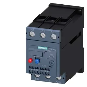
The Siemens 3RU2136-4KD1 is a SIRIUS-brand thermal overload relay in Size S2, designed to protect motors against overload and phase failure. The thermal bimetallic release compensates for ambient temperature changes across -40 to +60 °C, so the trip curve stays accurate whether the panel sits in a cold warehouse or a warm machine bay. Rated for a maximum of 690 V, the relay carries motor power ratings of 37 kW at 400 V, 45 kW at 500 V, and 55 kW at 690 V. The auxiliary contact block is integrated and provides signal ratings across multiple control voltages: 2 A at 24 V, 3 A at 120 V, 2 A at 230 V, and 1 A at 400 V. These are the values to check against your PLC input card or control relay coil draw — the 24 VDC rating at 2 A is sufficient for most digital inputs, but verify the inrush if driving a contactor coil directly.
This relay mounts in stand-alone installation — no DIN rail adapter required, though it can be snapped onto a 35 mm rail via the SIRIUS S2 base. Dimensions are 55 mm wide, 105 mm tall, 117 mm deep. The main circuit terminals accept screw-type connections with M6 screws; the auxiliary circuit accepts 2× (0.5 to 2.5 mm²) solid or stranded wire. Use a Pozidriv PZ2 screwdriver tip with a 5–6 mm shaft diameter.
Note on the 'Tripped' message
The spec record carries a note reading "for message 'Tripped'". This refers to the relay's auxiliary contact configuration: when the overload trips, the integrated auxiliary switch changes state to signal the condition. The 3RU2136-4KD1 is wired so that the normally-open contact closes on trip, sending a 'Tripped' signal back to the PLC or annunciator. Confirm the wiring diagram in the product documentation matches your control logic — some installations use the normally-closed contact in series with the contactor coil for direct shutdown.