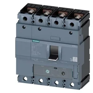
Breaking Capacity and Selectivity Planning
The 3VA1225-6EF42-0AJ0: Breaking capacity is the headline spec for an MCCB — it tells you the maximum fault current the breaker can safely interrupt. This 3VA1 delivers 220 kA at 240 V AC, 154 kA at 415 V, 75.6 kA at 440 V, 30 kA at 500 V, and 17 kA at 690 V. The steep drop above 500 V means you need to verify the available fault current at your service voltage. At 415 V, 154 kA covers most industrial main feeders; at 690 V, 17 kA is typical for motor control center incomers. Rated insulation voltage is 800 V, so the breaker is physically rated for 690 V systems.
Thermal Derating — Continuous Current vs Ambient Temperature
The 250 A rating holds at 40 °C, 45 °C, and 50 °C ambient. Above that, derating applies: 243 A at 55 °C, 237 A at 60 °C, 230 A at 65 °C, and 223 A at 70 °C. If this breaker sits in a non-air-conditioned enclosure near heat-generating equipment, use the 55 °C or 60 °C row for your continuous load calculation. Power loss at full load is 57 W — factor that into enclosure thermal rise. Dimensions are 158 mm high, 140 mm wide, 70 mm deep, fitting standard Siemens SENTRON mounting footprints.
Auxiliary Contacts and Wiring Integration
The breaker ships with 2 auxiliary switches plus 1 trip alarm switch (HP type). The auxiliary switches follow the main contact position; the trip alarm switch closes only on a fault trip (thermal or magnetic), not on manual open. This gives the PLC or BMS a dedicated fault signal without needing an external relay. No undervoltage release or shunt trip is included — those are separate accessories if required.
