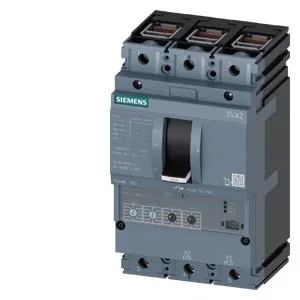
The Siemens SENTRON 3VA2110-5HN36-0KL0 is a 3-pole molded case circuit breaker rated for 100 A continuous current across the full ambient range from 40 °C to 70 °C — no derating needed up to that ceiling. It's designed for line protection in distribution panels, with a breaking capacity that starts at 187 kA at 240 V and holds 121 kA at 415 V and 440 V, then drops to 75.6 kA at 500 V and 3.7 kA at 690 V.
That simplifies panel sizing in hot environments like motor control centers or non-conditioned electrical rooms. The 3-pole construction covers three-phase loads; the line-protection design (not motor-protection) means it's set for cable and busbar protection, not overload curves matched to motor thermal damage. The shunt trip (STL) and the auxiliary switch complement (2 aux + 1 trip alarm + 1 electrical alarm) let you integrate remote tripping and status feedback into a PLC or safety circuit without an external interposing relay. Power loss is listed at 10 W maximum — modest for a 100 A frame, so heat buildup in a dense panel is manageable. The 86 mm depth, 105 mm width, and 181 mm height fit the standard SENTRON 3VA mounting footprint; if you're swapping from an older 3VA1 frame, check the depth — the 3VA2 series is slightly deeper than the 3VA1, so gland-plate clearance or door clearance may need a look.
The shunt trip (STL) and auxiliary switches are factory-fitted; verify the wiring diagram for the specific auxiliary switch configuration (2 aux + 1 trip alarm + 1 electrical alarm HQ) before terminating.