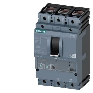
What this MCCB is and what it protects
The Siemens 3VA2163-5MN36-0KC0 is a 3-pole SENTRON molded case circuit breaker (MCCB) rated for 63 A continuous current, built specifically for motor protection duty. It carries an ETU350M electronic trip unit that provides adjustable overload and short-circuit protection, plus phase failure detection — a critical feature for three-phase motor loads where losing a phase can burn out a winding before the thermal overload catches it. The breaker ships with a factory-installed shunt trip (STL) release and two auxiliary switches (HQ type) for remote status feedback to a PLC or annunciator panel.
Breaking capacity — what the numbers mean for panel coordination
This MCCB delivers 187 kA interrupting capacity at 240 V AC, 121 kA at 415 V and 440 V, 75.6 kA at 500 V, and 17 kA at 690 V. Those figures are the maximum fault current the breaker can safely clear at each voltage level. For a 480 V panel in North America or a 400 V distribution board in Europe, the 121 kA rating gives substantial headroom above typical utility fault levels — useful when the breaker sits close to a large transformer or in a high-fault industrial service entrance. The 17 kA at 690 V still covers most 690 V motor circuits in mining or marine installations.
Thermal derating — real-world current capacity in a warm panel
The 63 A rating holds flat from 40 °C through 50 °C ambient. At 55 °C it derates to 60.48 A, at 60 °C to 59.22 A, at 65 °C to 57.96 A, and at 70 °C to 56.7 A. That derating curve matters when the breaker is enclosed in a non-ventilated panel alongside other heat-generating devices — a common scenario in motor control centers. If the panel ambient runs at 60 °C, the breaker's effective continuous current is 59.22 A, not 63 A. The maximum power loss at rated current is 75 W, which should be factored into the enclosure thermal budget.
Integration notes — what fits in the panel
The breaker measures 105 mm wide, 181 mm tall, and 86 mm deep — a standard 3-pole MCCB footprint that fits Siemens 3VA2 panelboards and most DIN-rail or mounting-plate layouts. The shunt trip (STL) is wired separately from the main power path; it requires a control voltage to trip the breaker on command, typically from an emergency-stop circuit or a remote undervoltage relay. The two auxiliary switches (HQ) provide one N/O and one N/C contact each, rated for the control circuit voltage. No undervoltage release is fitted, and there is no communication module or ground-fault monitoring on this variant.
