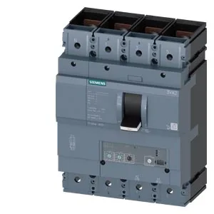
The 3VA2340-5HL42-0BL0 delivers 187 kA at 240 V, 121 kA at 415 V and 440 V, 75.6 kA at 500 V, and 7.5 kA at 690 V. For a site electrical engineer planning a selective coordination study: the high interrupting rating at the common 415 V level means this breaker can sit upstream of downstream devices with lower SCCR, provided the let-through energy (I²t) is coordinated. Compared to a sibling like the 3VA2225-5HN42-0BB0 (a 250 A frame), this 400 A unit occupies a larger physical footprint — 184 mm wide × 248 mm high × 110 mm deep — so a panel originally kitted for the smaller frame will need busbar re-spacing and possibly a different mounting base. The trip unit adjustment range (600 A to 4 000 A) also differs; the 250 A sibling's range tops out lower, so the two are not drop-in interchangeable without rewiring and re-coordination.
Thermal Derating and Installation Environment
Above that, it derates: 385 A at 55 °C, 370 A at 60 °C, 355 A at 65 °C, and 340 A at 70 °C. If your panel sits in a hot environment — near a furnace line, in a non-climate-controlled enclosure in the Gulf — you must apply the derating factor or risk nuisance tripping on thermal overload. The 110 mm depth and 184 mm width mean it fits standard Siemens SENTRON mounting bases and busbar systems. The line protection design (as opposed to motor protection) means the trip curve is optimized for cable and busbar thermal limits, not motor inrush — don't use it as a direct motor starter protector without checking the manufacturer's motor coordination tables.