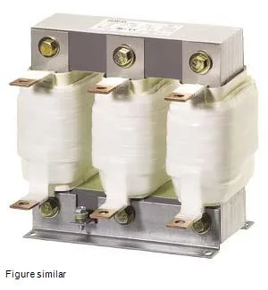
The Siemens SIDAC 4EU3021-2EA00-0A is a 3-phase output reactor rated for 400 V AC, with a maximum continuous current of 105 A and a rated operational current of 94.5 A. It is designed to sit between a variable-frequency drive and the motor, smoothing the voltage spikes and limiting the rate of voltage rise (dV/dt) that can cause winding insulation stress on long cable runs. The 7 kHz switching frequency rating means it is matched to the typical PWM carrier frequency of modern IGBT drives — not the motor's running speed, but the inverter's internal switching rate.
The 105 A maximum current (Ithmax) is the thermal rating for continuous duty under worst-case conditions; the 94.5 A operational current (I Ln) is the nominal value at which the inductance of 0.28 mH is specified. For a motor drive application, size the reactor so the motor's full-load current does not exceed the 94.5 A figure — the 105 A ceiling gives headroom for overloads but the inductance value shifts above the rated current. The 7 kHz switching frequency matches the carrier frequency of most general-purpose drives; if your drive runs at a higher PWM frequency (8–16 kHz), this reactor will still function but core losses will rise and derating may apply. Power loss is split between the coil (179.2 W) and the iron core (121 W), totaling about 300 W at full load. That heat must be dissipated into the surrounding air — the IP00 enclosure means no fan or ducting is built in, so the reactor relies on natural convection. Mount it with clearance around all sides; stacking or boxing it in without ventilation will push the winding temperature past the Class H (180 °C) insulation limit.
Output reactors (also called motor chokes) are installed on the output of a VFD to protect the motor from reflected-wave voltage spikes that occur when the cable run between drive and motor exceeds about 30 meters. This 3-phase unit with free cable endings (no terminal block) is intended for hardwiring into the panel — the installer strips and crimps ring lugs or ferrules onto the cable ends. The 0.21 m depth, 0.3 m width, and 0.26 m height mean it occupies a footprint roughly the size of a shoebox; plan for that volume in the enclosure layout, with clearance for the cable bends.
No successor order code has been issued.