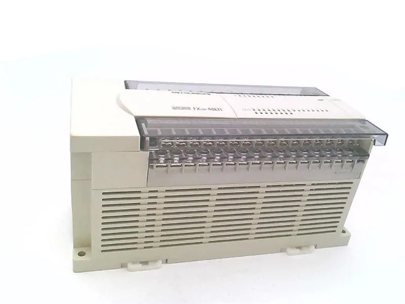
Mitsubishi Electric FX2N-48ER-ES/UL — PLCs (Programmable Logic Controllers)

FX2N-48ER-ES/UL Mitsubishi PLC, 24 in / 24 out relay

MPNFX2N-48ER-ES/UL
End of Life

Mitsubishi FX2N-48ER-ES/UL FX-series base unit, 24 DC inputs / 24 relay outputs, AC 100-240 V supply, removable M3 terminal blocks, lifecycle stage end-of-life.

$423.86 – $465.00Ref. price · indicative, final on quote
Sourced new & surplus through independent channelsAuthenticity-screened · ESD-safe packingListing updated Jul 2026

Specifications

FX2N-48ER-ES/UL key specifications
ParameterValue
Output type (format)relay
VoltageAC 100 V to 240 V
Withstand voltageBetween the power supply terminal (AC power supply) and the earth terminal: AC 1500 V for 1 minute tengah 24 VDC Service power supply and between the input terminal (24 VDC) and the earth terminal: 500 tengah V AC for 1 minute Between the output terminal (relay)
Input signal voltageDC 24 V ± 10%
Voltage tolerance rangeAC 85V ~ 264V
Inrush currentAC 100 V: maximum 40 A 5 ms or less tengah AC 200 V: maximum 60 A 5 ms or less
Input signal current5 mA / 24 VDC
Input ON sensitivity current3.5 mA or more
Input OFF sensitivity current1.5 mA or less
Power consumption35W
Power supply fuse250 V 5 A
External power supplyDC tengah 30 V or less AC 240 V or less (When not compliant with CE, UL, cUL standard, AC 250 V or less)

All specifications

FX2N-48ER-ES/UL additional specifications
ParameterValue
24 VDC service power supply24 VDC 460 mA or less When tengah connecting input / output extension block, 24 VDC service power is consumed.
Rated frequency50/60 Hz
Anti-vibration direct installation frequency57 to 150 Hz : Acceleration: 9.8 m / s 2 X, Y, Z 10 times in each direction (80 minutes in total) The tengah criteria are based on IEC 61131-2
Anti-vibration when DIN rail is installed frequency57 to 150 Hz : Acceleration: 4.9 m / s 2 Ten times in each of X, Y, Z directions (total of 80 minutes each) The tengah criterion is based on IEC 61131-2
Input connection shapeRemovable terminal block (M3 screw)
Output connection shapeRemovable terminal block (M3 screw)
Input response timeAbout 10 ms
Response time OFF ? ONAbout 10 ms
Operating temperature0 to 55 ° C. ··· Operating -25 to 75 ° C. ····· Save
Use altitudeCan not be used in an environment pressurized to 2000 m or less under atmospheric pressure. It may break down.
Relative humidity5 to 95% RH (noncondensing) · · · · in operation
Shipping weight2 Kg
Mass0.85 kg
GroundClass D grounding (grounding resistance: 100 O or less) tengah Grounding should be dedicated ground or common ground.
ON ? OFFAbout 10 ms
Input formatSink / source
Minimum loadDC 5 V 2 mA (reference value)
Inductive load80VA
Noise immunityNoise voltage with 1,000 Vp-p, noise width 1 µs, rising 1 ns, with noise si
Use atmosphereThere is no corrosive property, flammable gas, conductive dust (dust) is not serious
Input impedance4.3 kO
Impact resistance147 m / s 2 , working time 11 ms, tengah criterion for judgment three times in X, Y, Z directions by sine half-wave pulse is according to IEC 61131-2
Circuit insulationMechanical insulation
Estimated lead timeUsually ships in 1 - 10 working days.
Input signal formatSink: no-voltage contact input or NPN open collector transistor tengah contact input or PNP open collector transistor
Application sequencerFX1N, FX3G, FX2N, FX3U
Insulation resistanceBetween each terminal and earth terminal: 500 MV DC 500 MO or more with an insulation resistance meter
Number of input points24 points
Input operation displayLED on the panel when input is ON
Number of output points24 points
Input circuit insulationPhotocoupler insulation
Maximum load resistive loadtengah Please set the total load current per 2A / 1 point common as follows. tengah · Output 4 points / common: 8 A or less tengah · Output 8 points / common: 8 A or less
Output operation indicationLED lit when relay coil is energized

Product details

The Mitsubishi FX2N-48ER-ES/UL is a compact PLC base unit in the FX2N family, carrying 24 DC inputs and 24 relay outputs on a single 100-240 VAC supply — the unit that the cabinet gets built around when this FX-series footprint is on the BOM. I/O terminate on removable M3-screw terminal blocks at both the input and output ends, so a swap with a known-good spare (or a seasonal-output-stage rebuild) is a screwdriver operation rather than a wire-cut job. It drops into mixed FX-family installations: the unit is qualified as an application sequencer against the FX1N, FX3G, FX2N, and FX3U families, so a panel that has migrated generations can keep its I/O mapping intact.

Inputs — what the field-side card actually sees

Inputs accept DC 24 V ±10% in either sink or source wiring, drawing 5 mA at 24 VDC through a 4.3 kΩ input impedance — so a standard sensor barrel (PNP or NPN open-collector, or volt-free contact) lands on the same block without a rewire. The minimum-load reference is DC 5 V at 2 mA, which is the floor for a clean OFF-to-ON transition; mechanical reed switches and low-leakage sensors sit comfortably above this. Input response is about 10 ms in either direction, with photocoupler isolation between the field-side terminal and the internal logic. An on-panel LED per input confirms power-on state for the commissioning engineer walking the FAT — no meter required.

Outputs and 24 VDC service supply

All 24 outputs are volt-free relay contacts rated for inductive loads up to 80 VA, with an external switching envelope of 30 VDC or 240 VAC (250 VAC where CE / UL / cUL compliance is not at issue). The unit supplies its own 24 VDC service rail at up to 460 mA for sensor excitation and annunciator loops, but the rail is consumed by any input/output extension block that gets added — budget accordingly when adding an FX2N-16EX-ES/UL-class expander.

Power budget, environment, and protection

Mains side runs on AC 100 V to 240 V (tolerance 85-264 V) at 50/60 Hz, drawing 35 W with a 5 A / 250 V fuse on the supply — inrush on cold start is capped at 40 A (100 V) or 60 A (200 V) for ≤5 ms, so a standard C-curve breaker upstream is sufficient. Dielectric withstand is 1500 VAC for one minute between the AC power terminal and ground, and 500 VAC between the 24 VDC rail and ground, with 500 MΩ insulation resistance per terminal to earth — the numbers a safety auditor will read first. Operating envelope is 0–55 °C at 5–95% RH non-condensing, with storage to -25–75 °C, and impact tested at 147 m/s² for 11 ms to IEC 61131-2 sine half-wave per X/Y/Z — adequate for panel-mount, light-vibration industrial floors; pressurised-altitude use (≤2000 m absolute) is the documented hard boundary.

Second-source question — does this drop in for FX2N-16EX-ES/UL

No: the FX2N-16EX-ES/UL is an input expansion block, not a CPU/base unit. It cannot be substituted for a 48ER base — a panel that has the 48ER on its BOM line needs the 48ER, full stop. They sit on the same FX2N backplane family and can co-exist (the 16EX as an expander), but they are not cross-shop candidates.

Compliance documentation

The order code suffix /ES/UL denotes CE, UL, and cUL compliance on the underlying spec, with the note that AC 250 V external switching only applies where CE/UL/cUL is not in scope — a buyer should be ready to show the nameplate to a CE/UL inspector rather than rely on spec-sheet language alone. Dielectric test voltages (1500 VAC / 500 VAC) and IEC 61131-2 impact criteria are the documented compliance envelope; explicit RoHS / REACH statements are not on the spec sheet and would need to be sourced from the factory documentation pack on the unit's nameplate.

MPN
FX2N-48ER-ES/UL