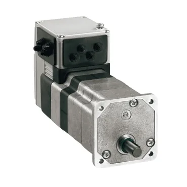
What the geared head delivers versus a bare BLDC
The ILE2P661PB1A5 is a Schneider Electric Lexium ILE integrated drive — a brushless DC motor with an on-board worm-gear reduction of 24:1 (525:22), so the controller, encoder feedback, and mechanical output live in one 229 mm-long, 66 mm flange package rather than the separate motor-plus-gearhead-plus-drive stack that a conventional servo build demands. Because the gearbox is internal, the 168 rpm nominal shaft speed at 24 V and 48 V already reflects the reduction — the buyer sizes against output rpm, not motor rpm, and the 33.6 lbf.in (3.8 N·m) nominal torque at both voltages is what reaches the load.
Electrical envelope and the 24/48 V decision
Supply limits span 18...55.2 V, so the same winding is driven from either a 24 V or 48 VDC bus; nominal torque of 33.6 lbf.in (3.8 N·m) and nominal output power of 45 W at 24 V versus 66 W at 48 V tell the integrator that stepping up the bus roughly lifts continuous mechanical power without changing the torque figure. Current draw peaks at 7000 mA with a 5500 mA continuous ceiling, so the upstream 24/48 V supply needs to budget that transient without tripping — natural-convection cooling means no fan is present and the 66 W continuous rating assumes an ambient that lets the housing shed heat without derating. Peak stall torque of 54.79 lbf.in (6.19 N·m) at both voltages defines the worst-case mechanical load the gearbox and shaft must absorb without slipping past the detent torque floor of 25.7 lbf.in (2.9 N·m).
Feedback, I/O, and the integrated protection set
A BLDC encoder on the motor side feeds back position with ±1 point accuracy, and four signals on the I/O connector can each be used as input or output — that configurability replaces the dedicated direction-enable-fault triad a discrete drive would expose. Built-in protection covers short circuit of the output voltage, safe torque off, and overload of output voltage, which is the standard STO-plus-output-guard package for an integrated drive at this class — the wiring diagram and STO wiring are the spec items to confirm before commissioning. Connection is through a printed circuit board connector rather than a flying lead, so panel builders plan for a mating header on the host PCB and route the 24/48 V bus and I/O signals to that footprint.
Mechanical fit, environment, and compliance
Flange mounting on a 66 mm motor flange with a hole-type shaft end and no second shaft gives a clean bolt-on install — the 9.02 in (229 mm) length is the dimension that drives the cabinet depth and the clearance behind the driven load. Vibration resistance of 20 m/s² over 10...500 Hz and shock resistance of 150 m/s² for 1000 shocks put the unit inside the EN/IEC 60068-2 envelope — adequate for general industrial mounting, though not for a high-shock mobile platform without further qualification. Operating altitude is rated up to 3280.84 ft (1000 m) without derating and humidity sits at 15...85 % non-condensing, while the CE mark is backed by the EN/IEC 61800-3, EN/IEC 50178, EN 50347, and IEC 60072-1 standards family — the EMC and dimensional baselines a European integrator expects for an integrated drive.