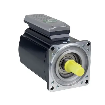
What kind of drive is this and where it drops into a PacDrive 3 line
The ILM1402P12A0000 is a Schneider Electric PacDrive 3 servo motor with the drive electronics integrated into the motor body — no separate drive cabinet slot, no external power stage between the controller and the rotor. That integration collapses the cabinet count on a PacDrive 3 machine: one cable set per axis, the Lexium-style feedback and power loop closed inside the motor housing. Mechanical envelope is a 140 mm flange, 12.2 in (309 mm) overall length, with a 4-hole standard flange pattern on 11 mm mounting holes and a 130 mm centring collar. That footprint maps cleanly to the PacDrive 3 machine-builder catalogues for mid-range axes — secondary packaging, label applicators, small-form indexing tables — where the cabinet space freed by an integrated drive is more valuable than the additional heat the integrated stage puts near the process.
Sizing envelope — torque, speed, and the inertia the controller sees
The electrical side: nominal line current 3.7 A, continuous stall current 4.8 A, peak Irms 24 A — the 24 A peak is the figure that matters when sizing the upstream 24 VDC/control power supply and the braking resistor duty, not the 3.7 A nominal. Nominal output power 1910 W lines up with the mechanical 9.1 N.m × 2000 rpm, so the sizing math closes. Back-EMF constant 173 V/krpm at 20 °C and torque constant 2.6 N.m/A at 120 °C tell the commissioning engineer what the controller will report on the fieldbus: at 2000 rpm the motor generates roughly 346 V back-EMF (cold), and the iq/torque scaling is calibrated against the hot constant, not the cold one — derate logic in the PacDrive 3 firmware uses the 120 °C figure.
Feedback, shaft, and the brake option that ships on this build
Feedback is an absolute multiturn SinCos Hiperface encoder, 128 periods — no battery-backed singleturn card to fail, no homing routine on power-up. Multiturn Hiperface on a PacDrive 3 axis means the machine position is retained through power cycles, which matters for vertical axes and indexed conveyors where the homing move would otherwise interrupt the cycle. Shaft is keyed, 24 mm diameter, 50 mm length, no second shaft end, no holding brake. Without the holding brake the axis cannot hold position with the power removed — for a vertical or unbalanced load a brake option must be sourced as a different build, or a mechanical brake added downstream of the gearbox. Confirm the BOM line specifies the brake variant if the machine needs fail-safe holding.
Mechanical loading, sealing, and what IP54 actually covers
Maximum radial force Fr is 2430 N at 1000 rpm, dropping to 1930 N at 2000 rpm — belt and pinion sizing has to respect the speed-dependent curve, not just the static load. Maximum axial force Fa is 0.2 × Fr, so a typical 1930 N radial rating permits only about 386 N of axial thrust before the bearing load curve starts clipping the catalogue figure. IP54 is dust-protected and splash-resistant, not washdown-rated. Cooling is natural convection — the motor relies on its surface area and the cabinet air, so a sealed cabinet with stagnant air will derate the continuous torque figure. This build belongs inside a panel on a packaging or assembly line, not on the wet end of a food-and-bev washdown zone.
Production status and how this part is sourced
Quoted to order against the BOM from independent distribution — the motor and its integrated drive stage are specified by exact build code, so confirming the keyed shaft, brake option, and feedback resolution at quote time is what prevents a wrong-axis delivery. No stock count, lead-time figure, or pricing is published here; both are confirmed at RFQ.