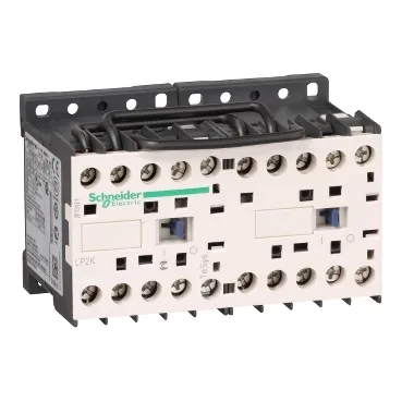
It is designed for resistive load switching (AC-1 utilisation category) in control circuits, not for motor starting duty. This is a plate- or rail-mountable component rated for a 20 A thermal current (Ith) at 50 Hz, with a power circuit impedance of 3 mOhm. The preassembled busbar and interlock eliminate the need to wire two separate contactors for reversing — a single part number covers the reversing pair in a compact 90 × 58 × 57 mm footprint.
The 48 V DC coil has an operational voltage range of 0.8 to 1.15 Uc (38.4 to 55.2 V DC) and a dropout threshold of 0.1 to 0.75 Uc (4.8 to 36 V DC) at <50 °C. Hold-in power consumption is 3 W at 20 °C. The operating time is 30–40 ms for coil energisation and NO closing, and 10 ms for coil de-energisation and NO opening. Rated insulation voltage (Ui) is 600 V per UL 508 and CSA C22.2 No 14, and 690 V per IEC 60947-4-1. The rated breaking capacity reaches 110 A at 440 V, 80 A at 500 V, and 70 A at 660–690 V per IEC 60947. The making capacity (Irms) is 144 A AC for the power circuit per IEC 60947. Associated fuse rating for the power circuit is 25 A gG or 25 A aM. Maximum operating rate is 3600 cycles per hour. Mechanical durability is 5 million cycles; electrical durability is 0.3 million cycles at 20 A, AC-1, ≤440 V. Safety reliability data per EN/ISO 13849-1: B10d = 1,369,863 cycles with nominal load, and B10d = 20,000,000 cycles with mechanical load only.
This contactor is certified to VDE 0660, IEC 60947, BS 5424, and NF C 63-110. Flame retardance is V1 per UL 94, and Requirement 2 per NF F 16-101/102. Overvoltage category is III. IP20 degree of protection per VDE 0106. Operating altitude is 2000 m without derating. Protective treatment is TC per IEC 60068 and DIN 50016. Mechanical robustness is verified to 15 Gn shocks (closed) and 4 Gn vibrations (closed) per IEC 60068-2-27 and IEC 60068-2-6.
For a BOM line requiring a reversing contactor pair with mechanical interlock and 48 V DC control, this part eliminates assembly labour and interlock wiring. Confirm fit by verifying the AC-1 resistive load rating (20 A Ith) and the 4-pole configuration against your circuit requirements.
Termination and Mounting Notes
Screw clamp terminals accept 1 or 2 conductors: solid 1.5–4 mm², flexible without ferrule 0.75–4 mm², or flexible with ferrule 0.34–2.5 mm² (single) / 0.34–1.5 mm² (double). Tightening torque is 1.3 N·m using a Philips No 2 or 6 mm flat screwdriver. Mounts on plate or DIN rail. The 90 mm width and 58 mm height fit standard control panel layouts. Heat dissipation is 3 W — account for this in enclosure thermal calculations when grouping multiple contactors.