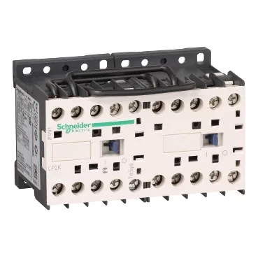
The 125 V DC coil pulls in the main poles and the mechanical interlock between the two contactors prevents both halves from closing simultaneously — a standard requirement for reversing motor starters or dual-source transfer circuits where cross-conduction is a fault. The 4-pole layout gives you two poles per contactor half for the line and two for the load, or you can parallel poles for higher current on a single leg — the average impedance per pole is 3 mOhm at 20 A, so voltage drop across the power circuit stays under 60 mV per pole at full load. Mounts to a plate or DIN rail (the 57 mm depth and 90 mm width fit a standard 8-module enclosure footprint). IP20 finger-safe terminals mean it can live on a backplate without an additional cover in most control panels.
The 125 V DC coil is the main selection gate. The control circuit is DC standard, with an operating range of 0.8 to 1.15 Uc (100 to 144 V DC) and a drop-out band of 0.1 to 0.75 Uc (12.5 to 94 V DC) below 50 °C. If your control bus is 110 V DC nominal, this is a direct fit; if it's 24 V DC, you need the 24 V DC coil variant. The hold-in power draw is 3 W at 20 °C — negligible for a PLC output but worth budgeting if the coil is held continuously on a UPS-backed supply. Breaking capacity is 110 A at 440 V, 80 A at 500 V, and 70 A at 660–690 V per IEC 60947. The rated making capacity is 144 A AC — enough to close into a cold filament load without contact bounce welding. Electrical durability is 0.3 million cycles at 20 A AC-1 up to 440 V. Mechanical durability is 5 million cycles. For a reversing contactor that cycles once per motor direction change, that's roughly 300,000 reversals before the contacts need inspection — a solid service life for a conveyor or pump station. Safety reliability is quantified: B10d of 1,369,863 cycles at nominal load and 20 million cycles at mechanical load per EN/ISO 13849-1. That places it in the high-reliability range for safety-related stop circuits where the contactor is the final switching element.
The preassembled reversing busbar saves panel-build time — no cutting and torquing jumper wires between two separate contactors. The mechanical interlock is factory-set, so you don't need to align the interlock bracket on the DIN rail. Just land the line and load wires, connect the coil common and the two control signals (forward/reverse), and the reversing pair is live. Screw-clamp terminals accept one or two conductors: 1.5–4 mm² solid, 0.75–4 mm² flexible without ferrule, or 0.34–2.5 mm² flexible with ferrule. Torque to 1.3 N·m with a #2 Phillips or 6 mm flat-blade screwdriver. The terminal layout is the standard TeSys K footprint, so a pre-wired panel can swap in this reversing pair without re-looming the wireway. Heat dissipation is 3 W per contactor (6 W total for the reversing pair). In a sealed enclosure with no forced ventilation, that's a modest thermal load — about 20 BTU/h — so it won't drive the internal temperature above the 40 °C derating threshold for most control components.
Compliance documentation covers the major industrial markets: designed to IEC 60947-4-1, UL 508 (600 V insulation), CSA C22.2 No 14, and VDE 0660. The IP20 finger-safe rating meets VDE 0106. Flame retardance is V1 per UL 94. For a panel destined for North America or Europe, the approvals are already in place.