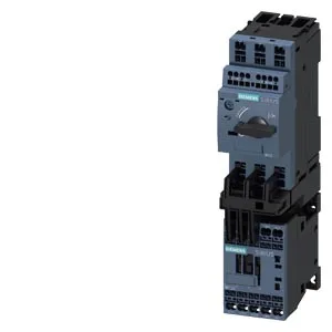
90 kW at 400 V — S00 direct online starter
The 3RA2115-0DE15-1FB4: The 24 V DC coil means it picks up directly from a PLC digital output or a 24 V control transformer without an interposing relay. The integrated assembly ships with a 3RT2015-2FB41 contactor, a 3RV2011-0DA25 circuit-breaker, and a 3RA2911-2AA00 link module — the three pieces are pre-coordinated for Type 2 coordination, so you get a single order code that covers the motor branch circuit protection, switching, and overload. The thermal bimetallic overload release is set to Class 10 trip curve, meaning it clears a stalled-rotor condition fast enough to protect the motor winding before the temperature rise exceeds the insulation class.
45 mm wide — DIN-rail footprint and clearances
The mounting method is screw and snap-on — the DIN rail latch engages first, then the screw secures it against vibration. Vertical mounting position is specified; the upwards clearance of 50 mm and forwards clearance of 20 mm are the minimums needed for wiring access and heat dissipation from the bimetallic overload. The main current circuit uses spring-loaded terminals — strip the wire, push it in, no screwdriver needed for the power connections. The control circuit termination is not specified in this data, but the 24 V DC coil wiring typically lands on the link module's screw terminals. Depth is 97 mm from the DIN rail backplane to the front of the housing, so a 100 mm deep enclosure leaves just enough clearance for the wiring ducts.