Active production — what that means for your BOM line
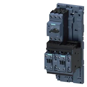
The 3RA2220-4EB27-0AK6: The unit ships as a factory-assembled combination: a 3RT2027-1AK60 contactor paired with a 3RA2921-1AA00 link module, pre-configured for reversing duty. No separate interlock wiring or mechanical linkage to source.
29 A AC-3 at 400 V — the rating that decides the motor
The AC-3 switching capacity is 29 A at 400 V, which corresponds to 15 kW motor load at that voltage. That is the figure to match against your motor nameplate FLA — not the thermal overload setting, but the contactor's ability to break the motor inrush without welding. The AC-3e rating mirrors the AC-3 figure at 29 A, confirming the electronic overload coordination. That is the standard for standard-start induction motors; if you are running a high-inertia load that needs a longer acceleration ramp, CLASS 10 may nuisance-trip.
Coil voltage and control wiring
The coil accepts 88–121 V at 50 Hz and 96–132 V at 60 Hz. That is a standard control transformer secondary range — 110 V or 120 V nominal. No separate DC supply needed; this is an AC-operated contactor. Main circuit terminals are screw-type, sized for the S0 feeder. The control circuit terminals are also screw-type on the link module. Torque to the values stamped on the contactor housing — overtightening strips the threads in the thermoplastic base.
Mounting and panel fit — DIN rail or screw
Mounts on a 35 mm DIN rail via the included adapter, or directly with screws through the base. The mounting position must be vertical — horizontal mounting changes the thermal overload calibration. Dimensions: 120 mm deep, 90 mm wide, 265 mm tall. Clearance: 50 mm above, 32 mm in front, 10 mm at the sides and below. The S0 frame size means the contactor and overload share the same width — no extra panel space for the reversing interlock.
Environmental limits and compliance
Operating temperature range is -20 to +60 °C with temperature compensation active across that band. Storage and transport: -50 to +80 °C.