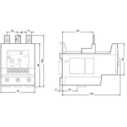
Siemens 3RB2046-1EW1 — Overload Relays

Siemens 3RB2046-1EW1 SIRIUS Solid-State Overload Relay, CLAS

MPN3RB2046-1EW1

Siemens SIRIUS solid-state overload relay, 3-pole, CLASS 10E, ATEX Ex II (2) GD, screw-type terminals, 124 × 70 × 106 mm.

Source DocumentedChannel stated on listing & quote
Condition PhotosReal unit photos / video on request
WhatsApp AnswersFast human replies for machine-down parts
Worldwide DispatchDHL/FedEx — transit quoted per order
Independent China distributor & sourcing agent· Listing updated Sep 2026

Specifications

3RB2046-1EW1 — Identification
ParameterValue
Product brand nameSIRIUS
Product designationsolid-state overload relay
Combinable contactor sizesS3
Reference code (IEC 81346-2)F
3RB2046-1EW1 — Protection & Trip
ParameterValue
Overload current setting range25 ... 100 A
Trip classCLASS 10E
3RB2046-1EW1 — Electrical (main circuit)
ParameterValue
Poles (main circuit)3
Rated insulation voltage (AC, pollution degree 3)1 000 V
Rated surge withstand voltage8 kV
Main current circuitstraight-through transformers
Power loss at rated current (hot)0.05 W
Per pole0.02 W
3RB2046-1EW1 — Auxiliary contacts
ParameterValue
Auxiliary contacts: NO1
Auxiliary contacts: NC1
Auxiliary contacts: CO (changeover)0
Auxiliary switch short-circuit protection (required fuse)fuse gL/gG: 6 A
Switching current at 24 V2 A
Switching current at 60 V0.55 A
Switching current at 110 V0.3 A
Switching current at 120 V4 A
Switching current at 125 V0.3 A
Switching current at 220 V0.11 A
Switching current at 230 V3 A
3RB2046-1EW1 — Connection & Mounting
ParameterValue
Mounting / fastening methodstand-alone installation
Mounting positionany
Auxiliary/control circuit connection typescrew-type terminals
Removable aux./control terminalYes
Conductor cross-section: solid0.5 ... 4 mm², 2x (0.5 ... 2.5 mm²)
Conductor cross-section: finely stranded with ferrule0.5 ... 2.5 mm², 2x (0.5 ... 1.5 mm²)
Conductor range (AWG), auxiliary contacts2x (20 ... 14)
3RB2046-1EW1 — Environmental
ParameterValue
Operating temperature-25 ... +60 °C
Storage temperature-40 ... +80 °C
Transport temperature-40 ... +80 °C
Relative humidity, operating100 %
Max. installation altitude2 000 m
Shock resistance15g / 11 ms
3RB2046-1EW1 — Mechanical
ParameterValue
Width70 mm
Height106 mm
Depth124 mm
3RB2046-1EW1 — Specifications
ParameterValue
Type Of ProtectionPTB 06 ATEX 3001 Ex II (2) GD

Product details

For a motor that starts against a heavy inertial load (centrifuge, crusher), you would step up to CLASS 20 or 30 — this one is sized for the faster-starting majority. The auxiliary circuit carries one NC contact (no CO contacts) rated at 24 V / 2 A, 120 V / 4 A, and 230 V / 3 A — these are the switching limits for the signal side, not the main power path. The 4 A at 120 V is the highest rating on the table, so that is the contact's maximum resistive switching capacity; at 24 V the 2 A limit reflects the lower voltage's reduced arc-quenching ability in a DC circuit. The screw-type terminals accept solid conductors from 0.5 to 4 mm² (or 2× 0.5 to 2.5 mm²) and finely stranded with ferrule from 0.5 to 2.5 mm² (2× 0.5 to 1.5 mm²).

The clearance requirements are minimal: 0 mm upwards, forwards, backwards, and downwards, with only 6 mm needed at the side. That means it can be packed against other devices on three sides without derating, as long as the side gap is respected. Dimensions are 124 mm deep, 70 mm wide, 106 mm tall — a compact footprint for a 3-pole solid-state unit. Rated for operation from -25 to +60 °C, storage and transport from -40 to +80 °C, and 100 % relative humidity during operation — so it handles condensing environments in washdown zones or outdoor cabinets without conformal-coat worries. Shock resistance is 15 g for 11 ms, adequate for mounting on a machine frame or near a vibrating conveyor drive.

Surge voltage resistance is rated at 8 kV, and burst immunity per IEC 61000-4-4 is 2 kV on power ports and 1 kV on signal ports (severity degree 3). That puts it in the standard industrial immunity class for a control panel fed from a typical 400 V distribution network with no special filtering. The substance prohibition date of 07/01/2006 aligns with the original EU RoHS directive — the part is RoHS-compliant for the current EU and UKCA markets.

Frequently asked questions

What compliance documentation does this part carry?

It carries ATEX approval PTB 06 ATEX 3001 Ex II (2) GD for gas and dust hazardous areas. Surge voltage resistance is 8 kV, and EMC burst immunity per IEC 61000-4-4 is severity degree 3 (2 kV power ports, 1 kV signal ports). The substance prohibition date of 07/01/2006 indicates RoHS compliance.

What are the key ratings for the auxiliary contact?

The single NC auxiliary contact is rated 2 A at 24 V, 4 A at 120 V, and 3 A at 230 V. These are the maximum switching capacities for the signal circuit — the main motor current is handled by the straight-through transformers, not this contact.

What conductor sizes does the screw terminal accept?

Solid conductors: 0.5 to 4 mm² (or 2× 0.5 to 2.5 mm²). Finely stranded with ferrule: 0.5 to 2.5 mm² (or 2× 0.5 to 1.5 mm²). For AWG on auxiliary contacts: 2× 20 to 14 AWG.

What clearance is needed around the device?

Clearance is 0 mm upwards, forwards, backwards, and downwards. Only 6 mm is needed at the side. This allows dense packing in the panel as long as the side gap is maintained.

MPN
3RB2046-1EW1