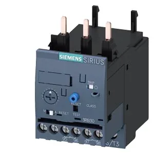
It's the component that sits between your contactor and motor, watching for overcurrent conditions and tripping on a CLASS 20E curve — that means it allows a 20-second overload at 7.2× the current setting before it opens, which is the standard match for standard-duty induction motors starting under load. The integrated auxiliary switch gives you a separate signaling contact (Note: for message "tripped") so the PLC or annunciator knows exactly when the relay has operated.
Mounting and wiring reality
This relay mounts directly onto the contactor — no DIN rail needed, no extra bracket. Fastening method is contactor mounting, so it clips onto the matching SIRIUS contactor and the power connections pass through. The main circuit uses screw-type terminals accepting 1x (0.5...4 mm²) solid or 2x (0.5...2.5 mm²) stranded, and the main contacts take M4 screws. For the power wiring, stranded 2x 10 mm² is also listed. The auxiliary contact terminals use a smaller Pozidriv PZ 2 screwdriver tip. Overall dimensions: 45 mm wide, 87 mm high, 84 mm deep — it's a compact S0 footprint that fits into standard panel layouts without surprises.
The 32 A thermal current is the continuous current the relay can carry without tripping — that's the number you match to your motor's full-load amps. The CLASS 20E trip class means the relay won't nuisance-trip on a normal motor start but will clear a sustained overload before the motor insulation takes damage. The auxiliary contact ratings tell you what the signaling circuit can handle: 2 A at 24 V, 4 A at 120 V, 3 A at 230 V — all AC values for the "tripped" signal contact. Shock resistance of 15g / 11 ms and vibration resistance per IEC 60068-2-27 mean it survives the typical bumps of a running machine.