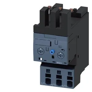
It mounts directly onto a contactor — no DIN-rail bracket needed — and uses spring-loaded terminals for the main circuit, which saves time during panel wiring. The adjustable trip class (5E, 10E, 20E, or 30E) lets you match the relay's response to the motor's starting characteristics: a pump with a long acceleration ramp gets class 30E; a fast-cycling conveyor motor gets class 5E.
The 12 A thermal current (Ith) is the continuous current the relay's main path can carry without exceeding temperature rise limits. For motor protection, the trip threshold is set by the current setting range: the relay trips when the motor current exceeds the upper setting value by a factor of 3.5 and resets when it drops below the lower setting value. The adjustable trip class gives you control over how long the relay waits before tripping on a locked-rotor condition — class 10E is the standard for most induction motors, while class 20E or 30E accommodates high-inertia loads that take longer to start.
Signaling and Auxiliary Contact Ratings
The integrated signaling contact (the note for message "tripped") provides a dry contact output that changes state when the relay trips. It's rated for 2 A at 24 V, 4 A at 120 V, and 3 A at 230 V, among other voltages — enough to drive a PLC input, an alarm lamp, or a remote annunciator directly. The contact's shock resistance is 15g / 11 ms (9g / 11 ms in the tripped position), so it holds its state through moderate panel vibration without false signals.
Storage and transport limits extend from -40 to +80 °C. Vibration resistance covers 1-6 Hz at 15 mm amplitude and 6-500 Hz at 20 m/s² for 10 cycles — typical for industrial machinery. Mounting position is unrestricted, so you can orient it vertically, horizontally, or upside-down on the contactor.