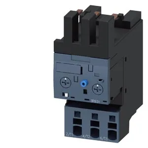
Siemens 3RB3123-4QE0 SIRIUS solid-state overload relay, 25 A
Siemens SIRIUS 3RB3123-4QE0 solid-state overload relay, Size S0, 25 A thermal current, adjustable trip class 5E/10E/20E/30E, 690 V rated voltage, spring-loaded terminals, contactor mounting.
Specifications
| Parameter | Value |
|---|---|
| Product brand name | SIRIUS |
| Product designation | solid-state overload relay |
| Frame size (overload relay) | S0 |
| Combinable contactor sizes | S0 |
| Reference code (IEC 81346-2) | F |
| Parameter | Value |
|---|---|
| Overload current setting range | 6 ... 25 A |
| Trip class | CLASS 5E, 10E, 20E and 30E adjustable |
| Overload release type | electronic |
| Parameter | Value |
|---|---|
| Rated operational current | 25 A |
| Poles (main circuit) | 3 |
| Rated operating frequency | 50 ... 60 Hz |
| Rated insulation voltage (AC, pollution degree 3) | 690 V |
| Rated value (AC-3e), max. | 690 V |
| Rated surge withstand voltage | 6 kV |
| Main current circuit | spring-loaded terminals |
| Power loss at rated current (hot) | 1.7 W |
| Per pole | 0.57 W |
| Parameter | Value |
|---|---|
| Auxiliary contacts: NO | 1 |
| Auxiliary contacts: NC | 1 |
| Auxiliary contacts: CO (changeover) | 0 |
| Auxiliary switch short-circuit protection (required fuse) | fuse gG: 6 A |
| Switching current at 24 V | 2 A |
| Switching current at 60 V | 0.55 A |
| Switching current at 110 V | 0.3 A |
| Switching current at 120 V | 4 A |
| Switching current at 125 V | 0.3 A |
| Switching current at 220 V | 0.11 A |
| Switching current at 230 V | 3 A |
| Parameter | Value |
|---|---|
| Mounting / fastening method | Contactor mounting |
| Mounting position | any |
| Main-circuit connector arrangement | Top and bottom |
| Auxiliary/control circuit connection type | spring-loaded terminals |
| Removable aux./control terminal | Yes |
| Conductor cross-section: solid | 2x (0.25 ... 1.5 mm²) |
| Conductor cross-section: solid or stranded | 2x (0,25 ... 1,5 mm²) |
| Conductor cross-section: finely stranded with ferrule | 2x (0.25 ... 1.5 mm²) |
| Parameter | Value |
|---|---|
| Operating temperature | -25 ... +60 °C |
| Storage temperature | -40 ... +80 °C |
| Transport temperature | -40 ... +80 °C |
| Relative humidity, operating | 10 ... 95 % |
| Max. installation altitude | 2 000 m |
| Shock resistance | 15g / 11 ms |
| Parameter | Value |
|---|---|
| Width | 45 mm |
| Height | 109 mm |
| Depth | 85 mm |
Product details
Frequently asked questions
What is the depth of 3RB3123-4QE0?
The depth is 85 mm. Overall dimensions are 45 mm width, 109 mm height, and 85 mm depth.
Will 3RB3123-4QE0 drop into a panel specified around 3RU2116-1FC1 without rewiring?
No. Both are Size S0 and share the same contactor mounting footprint, but the 3RB3123-4QE0 uses spring-loaded terminals while the 3RU2116-1FC1 uses screw terminals. The wiring method differs, so the panel would need terminal adaptation.
It mounts directly onto a contactor, making it a drop-in fit for motor starter assemblies where space on the DIN rail is already committed to the contactor footprint. The trip class is field-adjustable among CLASS 5E, 10E, 20E, and 30E, so the same relay can be tuned for fast protection on short-cycle loads or slower curves for high-inertia starts without stocking multiple variants. The main current circuit uses spring-loaded terminals, accepting solid conductors 2x (0.25 to 1.5 mm²) or stranded up to 1x 10 mm². The auxiliary contact ratings span 2 A at 24 V, 4 A at 120 V, and 3 A at 230 V, covering typical PLC and relay logic inputs.
Integration notes
Fastening method is contactor mounting — the relay clips directly onto the matching SIRIUS contactor, not onto a DIN rail. This saves one DIN slot per starter and keeps the overload relay mechanically ganged to the contactor for coordinated trip indication. Mounting position is any, so the assembly can be oriented horizontally, vertically, or flat without derating the thermal current. The relay withstands vibration per IEC 60068-2-6 at 1-6 Hz, 15 mm amplitude and 6-500 Hz, 20 m/s² for 10 cycles, and shock at 15g / 11 ms on the main body. The signaling contact (97/98) in the tripped position is rated for 9g / 11 ms.
Motor current setting and trip behavior
The relay trips when the motor current exceeds the upper current setting value multiplied by 3.5, and resets when the current falls below the lower current setting value. This hysteresis prevents nuisance cycling on momentary overloads. The note for message "tripped" indicates that the signaling contact changes state when the relay has operated — useful for wiring a remote alarm or PLC input that confirms the overload condition. Power dissipation is 0.57 W per pole, so a three-pole installation adds about 1.7 W of heat inside the enclosure — negligible for most panels but worth checking if the cabinet is densely packed and poorly ventilated.