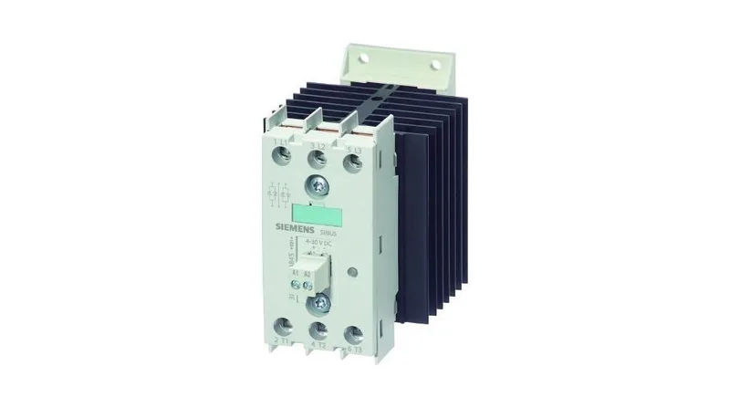
Solid-state contactor for resistive loads
The zero-point switching means the thyristors fire at the voltage zero crossing, which minimizes inrush and electrical noise on the line.
The 22 A AC-51 rating is the resistive load current — that's the number you use for heater banks, not motors. For motor or light inductive loads, you'd derate to the AC-53 curve (not listed here, but typical for this class). The minimum operational current is 500 mA, so it won't drop out on a small pilot load. The I²t maximum is 1 800 A²·s — that's the let-through energy the thyristors can handle during a short-circuit event before the upstream fuse clears. The evidence calls for a 3NA3805 fuse at 460 V, rated lower than the contactor itself, to protect the semiconductors. Wire it with screw terminals accepting 1x (0.5...2.5 mm²) solid or 2x (0.5...1.0 mm²) stranded. Control side draws 30 mA at 24 VDC nominal, with a 22 mA holding current. The DC control circuit is isolated from the main contacts — 7 mm clearance between them — so you can drive it from a PLC output without worrying about power-circuit noise coupling back.
45 mm wide, 100 mm tall, 117 mm deep — it takes up one standard DIN module width. Side-by-side mounting is allowed, but watch the 44 W heat dissipation and the 40 °C derating point. The UL 508 rating is 15 A — that's the US listing limit, which is lower than the IEC AC-51 rating. If your panel needs UL 508 compliance, size it at 15 A, not 22 A.