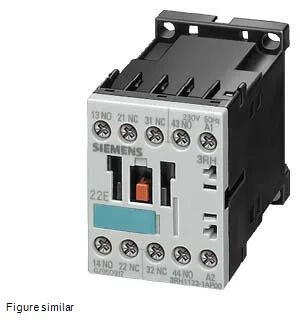
Its 2 normally-open and 2 normally-closed instantaneous contacts handle 10 A at 24 V, 6 A at 230 V, and 3 A at 400 V — so the 24 V figure is the high-current rating; at 400 V line voltage the contact current drops to 3 A, which is typical for auxiliary contacts in a 400 V control panel. Contact reliability is rated at one incorrect switching operation per 100 million cycles at 17 V, 1 mA — that's the dry-circuit performance for PLC-level signals. For general-purpose 24 VDC control loads the mechanical life of 30 million operations is the practical limit, not the electrical rating.
Lifecycle and compliance — active, RoHS dated
Shock resistance of 10 g for 5 ms and 5 g for 10 ms covers normal panel vibration and transport shock.
Wire termination — solid conductor cross-sections
The screw terminals accept solid conductors in three ranges: 2x (0.5 to 1.5 mm²), 2x (0.75 to 2.5 mm²), and 2x 4 mm². That means each clamp can take two wires of the same size, useful for daisy-chaining control voltage or signal common without a separate terminal block. The 4 mm² capacity handles the 10 A 24 V circuit without excessive voltage drop.
Mounting position and mechanical integration
Mounting position is standing on a horizontal surface — the contactor is designed for vertical DIN-rail orientation with the terminals facing up. Depth is 72 mm, height 57.5 mm, width 45 mm — the S00 envelope matches the standard contactor auxiliary block size, so it fits alongside S00 contactors in a grouped motor starter array without extra DIN-rail space.