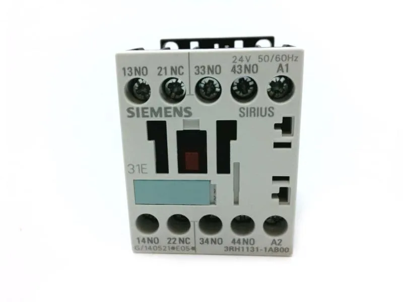
Siemens 3RH1131-2AF00-ZW96 — Contactors

Siemens 3RH1131-2AF00-ZW96 SIRIUS Auxiliary Contactor, Size

MPN3RH1131-2AF00-ZW96

Siemens SIRIUS auxiliary contactor, Size S00, order code 3RH1131-2AF00-ZW96, 3 NO + 1 NC, screw and snap-on mounting, IP20 front, rated 10 A at 24 V.

Sourced new & surplus through independent channelsAuthenticity-screened · ESD-safe packingListing updated Jul 2026

Specifications

3RH1131-2AF00-ZW96 — Identification
ParameterValue
Contactor frame sizeS00
3RH1131-2AF00-ZW96 — Ratings & Performance
ParameterValue
Rated operational current, AC-12, max.10 A
Rated value @ 400 V3 A
Rated value @ 500 V2 A
Rated value @ 690 V1 A
Rated value @ 230 V6 A
Rated value @ 24 V10 A
Rated value @ 110 V1 A
Rated value @ 220 V0.27 A
3RH1131-2AF00-ZW96 — Control & Coil
ParameterValue
Control supply voltage typeAC
Rated value @ 50 Hz0.8 ... 1.1
Rated value @ 50 Hz110 V
3RH1131-2AF00-ZW96 — Contacts & Poles
ParameterValue
Auxiliary contact reliability1 faulty switching per 100 million (17 V, 1 mA)
3RH1131-2AF00-ZW96 — Connection & Mounting
ParameterValue
Conductor cross-section, solid2x (0.25 ... 2.5 mm²)
Conductor cross-section, finely stranded w/ ferrule2x (0.25 ... 1.5 mm²)
Mounting methodscrew and snap-on mounting
3RH1131-2AF00-ZW96 — Durability
ParameterValue
Durability (operating cycles, typ.)30 000 000
Durability with aux. switch block (cycles, typ.)10 000 000
3RH1131-2AF00-ZW96 — Environmental
ParameterValue
Operating temperature range-25 ... +60 °C
Storage temperature range-55 ... +80 °C
Installation altitude, max.2 000 m
3RH1131-2AF00-ZW96 — Mechanical
ParameterValue
Width45 mm
Height60 mm
Depth73 mm

Product details

It provides 3 normally open (instantaneous) and 1 normally closed (instantaneous) contact set, with no delayed, lagging, or make-before-break switching — a straightforward, non-overlapping contact arrangement for standard interlocking and feedback circuits.

This contactor is rated for switching currents that vary with the applied voltage — a critical detail for sizing in control circuits. At 24 V the contacts handle 10 A; at 110 V the rating drops to 1 A, and at 230 V it is 6 A. For higher-voltage control schemes, the ratings are 3 A at 400 V, 2 A at 500 V, and 1 A at 690 V. These are not continuous thermal currents but the switching capacity under the specified conditions — derate further if switching inductive loads without suppression.

The unit withstands shock at 10g / 5 ms and 5g / 10 ms. RoHS compliance is declared with a substance prohibition date of 07/01/2006.

The terminal accepts solid conductors from 0.25 mm² up to 2.5 mm² per connection, with two conductors per clamp. This covers common control wiring sizes (AWG 24 to 14 solid).

MPN
3RH1131-2AF00-ZW96