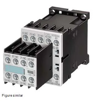
It provides four normally open (NO) instantaneous contacts, with no leading, lagging, or delayed switching — meaning all four close and open simultaneously with the coil. Rated for 10 A at 24 V (resistive), it also handles 6 A at 230 V, 3 A at 400 V, and 1 A at 690 V, covering the typical control-voltage range in European 400 VAC panels. The 6 kV rated surge voltage withstand gives it solid margin for transient-heavy environments like motor-starter cabinets.
The four NO contacts are rated for 10 A at 24 V, 6 A at 230 V, and 3 A at 400 V — these are the thermal (resistive) current ratings, AC-1 duty. For motor control circuits (AC-15), derate per the standard; the mechanical endurance of 30 million operations means this contactor will outlast most panel refreshes. Shock-rated at 10g / 5 ms and 5g / 10 ms, it's suited for applications with vibration from nearby contactors or motor starters. Contact reliability is specified as one incorrect switching operation per 100 million cycles at 17 V, 1 mA — useful for PLC-level signals where dry switching can be a problem.
Integration Notes
The depth includes the coil terminals and the snap-on latch. When panel-layout planning, allow at least 10 mm clearance below for wiring access. Coil ratings: 0.8–1.1 A at 50 Hz, 0.85–1.1 A at 60 Hz, both at 230 V.