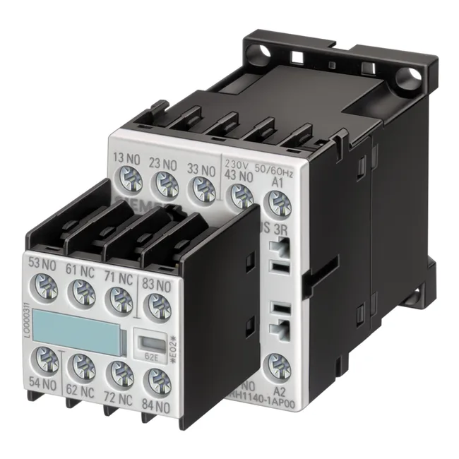
The Siemens 3RH1140-1BG40 is a SIRIUS auxiliary contactor in the size S00 frame — the compact footprint that mates directly with S00 power contactors on a DIN rail. It carries 4 instantaneous normally-open contacts, rated for a 125 V DC coil. The 45 mm width and 72 mm depth match the standard S00 contactor envelope, so it clips onto the same rail alongside the main contactor without extra panel space. This is the auxiliary block you add when the main contactor runs out of N.O. aux contacts — or when you need a separate control-circuit isolation path. The coil draws 3.2 W DC both on pick-up and hold, so the control transformer sizing is straightforward: no inrush spike to budget for.
The contacts are rated for switching at several common control voltages: 10 A at 24 V, 6 A at 230 V, 3 A at 400 V, 2 A at 500 V, and 1 A at 690 V. These are thermal current ratings for the auxiliary contacts — they govern the continuous current the contacts can carry, not the motor load. For a typical 24 V DC PLC output driving a solenoid or indicator, 10 A is generous headroom. At 230 V AC control circuits, 6 A covers most pilot-duty loads.
Mechanical endurance and mounting flexibility
Typical mechanical life is 30 million switching operations. Contact reliability is specified as one incorrect switching operation per 100 million at 17 V and 1 mA — that low-level switching capability matters when the auxiliary contacts are used to read dry-contact status inputs from sensors or limit switches. Shock resistance is 10g for 5 ms and 5g for 10 ms, covering most industrial vibration environments short of direct hammer strikes.
Terminals accept solid conductors: 2x 0.5–1.5 mm², 2x 0.75–2.5 mm², or 2x 4 mm². That covers standard control wiring from 18 AWG to 12 AWG. The screw-clamp terminals are the same type used on S00 contactors, so the same screwdriver and torque setting apply across the panel.
RoHS compliance date is 2006-07-01, covering the EU RoHS directive.