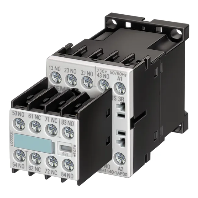
Four normally-open instantaneous contacts give you the basic building block for interlocking, status feedback, or PLC input isolation. There are no delayed, leading, or lagging contacts here — every contact closes and opens with the armature stroke, so timing is governed by the coil response of whatever device drives it.
The contact ratings are given per voltage, not as a single blanket current. At 24 V rated value it carries 10 A — that's the highest continuous current on the list and typical for DC control circuits. At 230 V rated value (50 Hz) it's 6 A, and at 400 V rated value it's 3 A. The 690 V rated value column drops to 1 A. These are the thermal current limits for the contact stack; derate further if you're switching inductive loads like small contactor coils or solenoid valves without suppression. Surge voltage resistance is rated at 6 kV, which aligns with basic insulation coordination for a 400 VAC control panel (pollution degree 3). That means the contactor can withstand transient overvoltages from switching inductive loads or nearby lightning without flashover across the open contacts or to ground. Contact reliability is specified as one incorrect switching operation per 100 million cycles at 17 V, 1 mA — a dry-circuit rating that matters if you're switching low-energy signals from sensors or PLC outputs. Most auxiliary contactors don't state this; the fact that Siemens does means the silver-alloy contacts are designed for light-load fidelity, not just power switching. The mechanical life of a typical S00 contactor is 30 million operations. That's not a wear-limit guarantee for the contacts under load, but it tells you the armature and spring mechanism are built for high-cycle applications like conveyor interlocking or press control where the auxiliary contacts cycle every machine stroke.
The S00 width of 45 mm means it occupies one standard module position on the rail. That covers most cabinet layouts except horizontal rail mounting. The contactor is intended for inside a cabinet with a higher enclosure rating. If your panel sees freeze-thaw condensation, the pollution degree 3 rating (conductive pollution) means the creepage distances are designed for occasional condensation, but you still want the cabinet sealed. Shock resistance is 10g for 5 ms and 5g for 10 ms. That's adequate for most industrial machinery but not for naval or heavy mobile equipment — if the panel is mounted on a vibrating conveyor or a press, you may need additional mechanical damping or a different contactor series.
Wiring and compliance
Solid conductor cross-section accepted is 2x (0.25 to 2.5 mm²). That's two conductors per clamp, which is useful for daisy-chaining control voltage or looping common wires through the contactor without extra terminal blocks. The 2.5 mm² upper limit handles standard 14 AWG control wiring; for longer runs or higher current you'd need to parallel terminals or step up to a larger contactor frame.