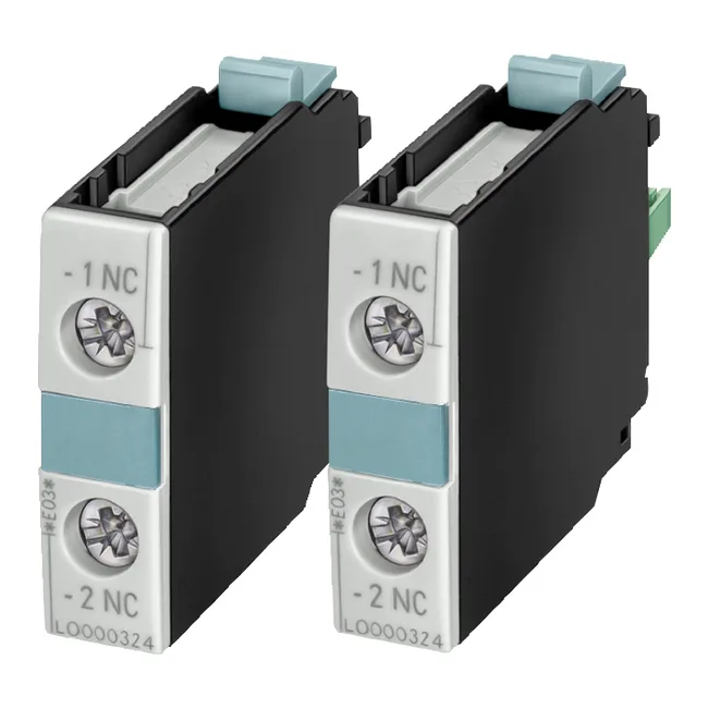
It adds one N/O mirror contact to the contactor or contactor relay, giving you a mechanically linked, positively driven auxiliary that signals the main contact position without relying on the coil state. The mirror contact meets IEC 60947-4-1 when used with a 3RT1 contactor, which means it's suitable for safety circuits where you need to verify the main contacts are open before allowing access or enabling a downstream device.
Switching capacity — what the voltage columns tell you
This switch carries two sets of current ratings because the contact performance changes with the load type. For the heavier AC-15 / DC switching duty typical of contactor coils, solenoid valves, and small motors, the ratings are lower: 6 A at 24 V, 2 A at 48 V and 60 V, 1 A at 110 V, 0.9 A at 125 V, 0.3 A at 220 V and 250 V, and 3 A at 400 V. The AC-12 number is your maximum continuous current; the AC-15 column governs the inrush when switching inductive loads.
Mounting and wiring in the panel
The 10 mm width means it adds minimal rail space; you can stack a second unit laterally if you need more auxiliary contacts. Screw-type terminals accept two conductors per clamp: solid or stranded from 0.5 to 2.5 mm² (AWG 20 to 14), or finely stranded with ferrules in the same range. Strip length is standard at 8–10 mm.