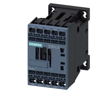
Active Production — SIRIUS Coupling Relay for Auxiliary Circuits
The 3RH2122-2LF40-1AA0: It is designed for switching auxiliary circuits in control panels, motor starter assemblies, and PLC output isolation stages. The size S00 frame keeps the panel footprint tight — 45 mm wide, 70 mm tall, 121 mm deep — and it mounts via screw or snap-on onto standard 35 mm DIN rail.
Switching Capacity Across the Voltage Range
The 2 instantaneous contacts (2 NO configuration) are rated for 10 A at 24 V, 10 A at 230 V, 3 A at 110 V, 3 A at 400 V, and 1 A at 690 V. The 0.26 A rating at 600 V and 0.5 A at 440 V define the AC load envelope at higher line voltages — this is a signal-level auxiliary relay, not a power contactor. The varistor surge suppressor is built into the coil circuit, protecting downstream PLC or controller outputs from back-EMF when the relay de-energises. Coil closing power at DC is 2.8 W — within the drive capability of a standard 24 VDC PLC output.
Mounting, Clearance, and Environmental Limits
Mount the relay standing on a horizontal surface. Minimum clearances to adjacent components: 10 mm upwards, 10 mm forwards, 10 mm downwards, and 6 mm at the sides. These spacings keep the arc quenching zone clear and prevent tracking in pollution degree 3 environments. Operating temperature range is -25 to +60 °C; storage range is -55 to +80 °C. The 10 % minimum relative humidity floor means the relay tolerates dry climates without seal degradation. Mechanical life is 30 million operations typical — the limiting factor is the contact wear under load, not the mechanism.
Sourcing and Compliance
RoHS compliance date is 10/01/2009 — the part meets the substance prohibitions effective from that date. The 2x (0.5 to 4 mm²) solid or stranded wire termination accepts standard control wiring without ferrule adapters.