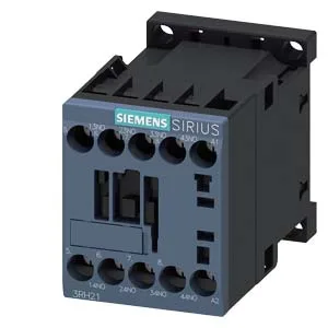
It is designed to switch control and signalling circuits in motor starter assemblies and general panel wiring, extending the auxiliary contact count of a main contactor or serving as a standalone interface relay.
Switching capacity — what the voltage/current table means for your circuit
The contactor's thermal current rating is 10 A at 24 V and 230 V, but the allowable switching current drops as voltage rises: 4.7 A at 60 V, 3 A at 110 V, 1.2 A at 220 V, 3 A at 400 V, 2 A at 500 V, 1 A at 690 V, and 0.26 A at 600 V. These are not derating curves — they are the maximum continuous current the contacts can carry at each voltage level, governed by the contact gap and arc-quenching capability. For a 400 V control circuit, for example, the 3 A limit means each NO contact can switch a modest pilot load or PLC input, but not a contactor coil drawing 4 A inrush. Rated surge voltage of 6 kV indicates impulse withstand for environments with transient overvoltages, consistent with pollution degree 3.
If you are comparing against the 3RH2140-1BP40 (a common alternate in the same S00 frame), the physical footprint and mounting are identical — same 45 mm width, same 73 mm depth, same DIN-rail clip. The difference is in the contact configuration and coil voltage; the -1AU60 has 4 NO contacts, while the -1BP40 carries a different contact arrangement. For a panel already drilled and wired for the -1BP40, the -1AU60 will drop into the same DIN slot without rewiring the mounting, but the contact wiring plan must match.
Environmental and integration notes
The 30 million mechanical cycles typical life means this auxiliary contactor outlasts most main contactors it accompanies; it is not the wear item in the starter assembly.