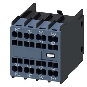
What this auxiliary switch does in your panel
It adds two instantaneous contacts to the base device, giving you feedback or interlock signals without extra wiring runs back to the PLC. The snap-on mounting means it clips directly onto the 3RH2140 or 3RH2440 auxiliary switch base — no tools needed, and it stays put under vibration in a panel cabinet. The 6 kV surge voltage resistance means it withstands switching transients on a 400 V line without flashover, which is what you need when the auxiliary contacts sit in the same enclosure as the power wiring.
This switch block carries two sets of current ratings: one for the standard switching duty and one for the rated value. At 24 V you get 6 A standard and 10 A rated value; at 110 V it drops to 1 A standard and 3 A rated value. The pattern tells you the contacts are silver-alloy and sized for DC control circuits where the arc stretches with voltage. If your BOM calls for switching a 24 VDC relay coil at 2 A, this part has headroom. If you need to break a 220 VDC solenoid at 1 A, the 0.3 A standard rating says you need a different block or a DC-rated interposing relay. That matters when the auxiliary switch feeds a PLC input that sees micro-amp leakage; you won't get false signals from oxidation.
Wiring and termination — what fits the terminals
The terminals accept two conductors per clamp: 2x (0.5... 2.5 mm²) solid or stranded, or 2x (20... 14 AWG). Finely stranded wire with ferrules goes up to 1.5 mm² per clamp. The spring-cage design holds the wire without retightening, but strip length matters — aim for 8–9 mm to avoid exposed copper past the cage.
Physical fit — dimensions for panel layout
The block measures 47.7 mm deep, 36 mm wide, and 41.5 mm high. The 36 mm width matches the standard S00 contactor footprint, so it doesn't widen the assembly beyond the base device. Depth of 47.7 mm includes the snap-on latch; plan for 50 mm clearance behind the panel door if you're mounting the contactor on a DIN rail.