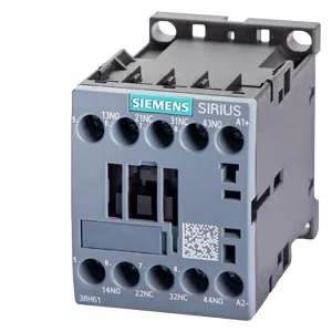
Siemens 3RH6122-1BM40 — Contactors

Siemens 3RH6122-1BM40 SIRIUS Contactor Relay, 220 V DC, 2 NO

MPN3RH6122-1BM40

Siemens SIRIUS contactor relay, size S00, 220 V DC coil, 2 NO + 2 NC auxiliary contacts, screw-type terminals, 45 mm width, 73 mm depth.

Sourced new & surplus through independent channelsAuthenticity-screened · ESD-safe packingListing updated Jul 2026

Specifications

3RH6122-1BM40 — Identification
ParameterValue
Contactor frame sizeS00
3RH6122-1BM40 — Ratings & Performance
ParameterValue
Rated operational current, AC-12, max.6 A
Rated value @ 400 V3 A
Rated value @ 690 V1 A
Rated value @ 230 V10 A
Rated value @ 24 V6 A
Rated value @ 110 V3 A
Rated value @ 220 V1.2 A
3RH6122-1BM40 — Control & Coil
ParameterValue
Control supply voltage typeDC
3RH6122-1BM40 — Contacts & Poles
ParameterValue
Auxiliary contact reliability1 faulty switching per 100 million (17 V, 1 mA)
3RH6122-1BM40 — Connection & Mounting
ParameterValue
Conductor cross-section, solid or stranded2x (0.5 ... 1.5 mm²), 2x (0.75 ... 2.5 mm²), 2x 4 mm²
Conductor cross-section, finely stranded w/ ferrule2x (0.5 ... 1.5 mm²), 2x (0.75 ... 2.5 mm²)
Mounting methodscrew and snap-on mounting onto 35 mm DIN rail
3RH6122-1BM40 — Durability
ParameterValue
Durability (operating cycles, typ.)30 000 000
Durability with aux. switch block (cycles, typ.)10 000 000
3RH6122-1BM40 — Environmental
ParameterValue
Operating temperature range-25 ... +60 °C
Storage temperature range-55 ... +80 °C
Installation altitude, max.2 000 m
3RH6122-1BM40 — Mechanical
ParameterValue
Width45 mm
Height57.5 mm
Depth73 mm
3RH6122-1BM40 — Specifications
ParameterValue
At AC10 000 1/h

Product details

The coil draws 4 W during both closing and holding, so there is no inrush-to-hold drop to account for in the DC supply sizing.

Contact configuration and switching capability

The relay provides two normally-open and two normally-closed auxiliary contacts (designation 22 E). Switching current is voltage-dependent: at 24 V DC it handles 6 A, at 110 V DC it handles 3 A, and at 220 V DC — the coil rating — it switches 1.2 A. The mechanical endurance is 30 million operations without an auxiliary switch block, or 10 million with one added. Contact reliability is specified at one faulty switching per 100 million operations under dry-circuit conditions (17 V, 1 mA), which is relevant for PLC-level signal integrity.

The 45 mm wide body clips onto 35 mm DIN rail and can be rotated ±180° on a vertical surface, or tilted ±22.5° forward and backward — useful when panel layout forces an unconventional orientation. Screw-type terminals accept two conductors per clamp: solid or stranded from 0.5 to 2.5 mm², or a single 4 mm². For AWG, that translates to 2x 20–16, 2x 18–14, or 2x 12. Strip length and torque are per the terminal marking; the spring-cage alternative is not fitted here.

Frequently asked questions

What is the contact configuration of the 3RH6122-1BM40?

It has two normally-open and two normally-closed auxiliary contacts, designated 22 E.

What is the coil voltage and power consumption?

The control supply voltage is 220 V DC. Both closing and holding power are 4 W.

What are the mounting dimensions?

Width is 45 mm, height is 57.5 mm, and depth is 73 mm. It mounts on 35 mm DIN rail.

MPN
3RH6122-1BM40