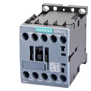
Siemens 3RH6131-1BM40 — Contactors

Siemens SIRIUS 3RH6131-1BM40 Contactor Relay, 1NC+3NO, DC 22

MPN3RH6131-1BM40

Siemens SIRIUS 3RH6131-1BM40 contactor relay, size S00, 1 NC + 3 NO auxiliary contacts, DC 220 V coil, screw-type terminals, snap-on 35 mm DIN rail.

Sourced new & surplus through independent channelsAuthenticity-screened · ESD-safe packingListing updated Aug 2026

Specifications

3RH6131-1BM40 — Identification
ParameterValue
Contactor frame sizeS00
3RH6131-1BM40 — Ratings & Performance
ParameterValue
Rated operational current, AC-12, max.6 A
Rated value @ 400 V3 A
Rated value @ 690 V1 A
Rated value @ 230 V10 A
Rated value @ 24 V6 A
Rated value @ 110 V3 A
Rated value @ 220 V1.2 A
3RH6131-1BM40 — Control & Coil
ParameterValue
Control supply voltage typeDC
3RH6131-1BM40 — Contacts & Poles
ParameterValue
Auxiliary contact reliability1 faulty switching per 100 million (17 V, 1 mA)
3RH6131-1BM40 — Connection & Mounting
ParameterValue
Conductor cross-section, solid or stranded2x (0.5 ... 1.5 mm²), 2x (0.75 ... 2.5 mm²), 2x 4 mm²
Conductor cross-section, finely stranded w/ ferrule2x (0.5 ... 1.5 mm²), 2x (0.75 ... 2.5 mm²)
Mounting methodscrew and snap-on mounting onto 35 mm DIN rail
3RH6131-1BM40 — Durability
ParameterValue
Durability (operating cycles, typ.)30 000 000
Durability with aux. switch block (cycles, typ.)10 000 000
3RH6131-1BM40 — Environmental
ParameterValue
Operating temperature range-25 ... +60 °C
Storage temperature range-55 ... +80 °C
Installation altitude, max.2 000 m
3RH6131-1BM40 — Mechanical
ParameterValue
Width45 mm
Height57.5 mm
Depth73 mm
3RH6131-1BM40 — Specifications
ParameterValue
At AC10 000 1/h

Product details

The Siemens SIRIUS 3RH6131-1BM40 is a contactor relay — a control-circuit switching device, not a power contactor for motor loads. Its switching element configuration is identified as 31 E, meaning 1 normally-closed (NC) and 3 normally-open (NO) auxiliary contacts. This gives you four independent contact paths for interlocking, signaling, or logic functions in a control scheme. The coil is rated for DC control voltage at 220 V, drawing 4 W during both closing and holding — a constant-power coil design that simplifies the DC supply sizing. The 6 kV rated surge voltage resistance means the coil insulation withstands the transients common on 220 V DC control buses in industrial panels.

That covers most panel layouts without needing a special bracket. Dimensions are 45 mm wide, 57.5 mm high, 73 mm deep — the S00 footprint. The screw-type terminals for auxiliary and control circuits accept 2x (0.5 to 1.5 mm²) solid/stranded, 2x (0.75 to 2.5 mm²), or 2x 4 mm². For AWG, that translates to 2x (20–16), 2x (18–14), or 2x 12 AWG. Finely stranded wire with core-end processing (ferrules) also fits the same cross-sections.

Switching ratings and contact reliability

At 24 V the contacts carry 6 A; at 110 V, 3 A; at 220 V, 1.2 A; at 230 V, 10 A; at 400 V, 3 A; at 690 V, 1 A. The 10 A at 230 V rating is the highest thermal current — that's the resistive load (AC-12) figure. For DC switching, the operating frequency maxes at 1 000 operations per hour for both DC-12 and DC-13. The mechanical endurance is 30 million switching cycles typical for the contactor relay alone, and 10 million typical when an auxiliary switch block is added.

Frequently asked questions

What is the contact configuration?

1 normally-closed (NC) and 3 normally-open (NO) auxiliary contacts, identified as switching element 31 E.

What coil voltage does it use?

DC 220 V control supply voltage. Coil power is 4 W for both closing and holding.

MPN
3RH6131-1BM40