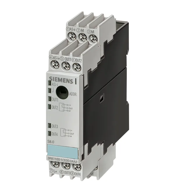
Siemens 3RK1100-1CQ01-0AA3 — Remote I/O & Fieldbus Modules

Siemens 3RK1100-1CQ01-0AA3 AS-Interface Module, 4 Outputs IP

MPN3RK1100-1CQ01-0AA3

Siemens AS-Interface digital I/O module, 4 transistor outputs, IP67, 45 x 80 x 27 mm, M12 connections.

Sourced new & surplus through independent channelsAuthenticity-screened · ESD-safe packingListing updated Aug 2026

Specifications

3RK1100-1CQ01-0AA3 — Identification
ParameterValue
Product designdigital I/O modules for operation in the field, IP67 - user modules
3RK1100-1CQ01-0AA3 — Communication
ParameterValue
AS-Interface supportYes
3RK1100-1CQ01-0AA3 — I/O
ParameterValue
Digital inputs0
3RK1100-1CQ01-0AA3 — Environmental
ParameterValue
Ingress protection (IP)IP67
Operating temperature range-25 ... +85°C
Storage temperature range-40 ... +85°C
3RK1100-1CQ01-0AA3 — Mechanical
ParameterValue
Width45mm
Depth27mm
Height80mm
Mounting methodstandard rail mounting/wall mounting using coupling module

Product details

AS-Interface Field Output Module, 4-Channel

The Siemens 3RK1100-1CQ01-0AA3 is a standard AS-Interface slave module providing four digital transistor outputs in an IP67-rated field enclosure. It is designed for distributed I/O in harsh environments, connecting via M12 screw-type connectors and mounting to standard rail or wall through a coupling module. Each output is rated for 1 A (DC-12/13), with a total aggregate current of 2 A across all four channels. The module requires an external auxiliary power supply of 20 to 30 V DC (PELV, protection class III) for the output circuits, separate from the AS-Interface bus power. The AS-Interface protocol is supported per the specification, with an operating voltage range of 26.5 to 31.6 V DC on the bus. The module draws up to 50 mA from the AS-Interface network for its internal logic.

Integration and Wiring Constraints

This module has four I/O sockets with a fixed pin assignment: PIN4 carries OUT1 (D0) on socket 1 and OUT3 (D2) on socket 3; PIN2 carries OUT2 (D1) on socket 1 and OUT4 (D3) on socket 3. Sockets 2 and 4 use PIN4 for OUT2 and OUT4 respectively. The input circuit is NPN type. An external 24 V DC supply must be provided, typically via the black flat cable in the AS-Interface system. The module includes built-in short-circuit protection and induction protection on the outputs. Status indication is via yellow LEDs for I/O states and a multi-color LED for AS-Interface diagnostics: green for normal operation, red for no data traffic, flashing red/yellow for zero address, and flashing red for sensor overload.

For BOM verification, the module carries the reference code K per EN 61346-2. The ID code on the AS-Interface bus is 1.

Frequently asked questions

What is the output configuration and current rating?

The module provides 4 digital transistor outputs, each rated for 1 A (DC-12/13), with a total aggregate current of 2 A across all outputs. An external 24 V DC auxiliary supply is required.

What is the IP rating and mounting method?

The enclosure is rated IP67 for dust and water ingress protection. It mounts to standard rail or wall using a coupling module.

Does this module require an external power supply?

Yes, an external auxiliary supply of 20 to 30 V DC (PELV, protection class III) is required for the output circuits. This is separate from the AS-Interface bus power.

What is the connector type and pin assignment?

The I/O connections use M12 screw-type connectors. Pin assignments vary by socket: for example, socket 1 uses PIN4 for OUT1 and PIN2 for OUT2; socket 3 uses PIN4 for OUT3 and PIN2 for OUT4.

MPN
3RK1100-1CQ01-0AA3