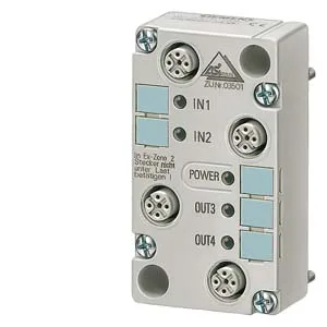
AS-Interface field module, 2 inputs / 2 outputs, IP67
The Siemens 3RK1400-1BQ01-0AA3 is an AS-Interface digital I/O module rated for 2 inputs and 2 outputs, housed in an IP67-rated enclosure for direct field mounting on machinery or conveyor sections without a control cabinet. Inputs are NPN type with a switching threshold at 10 V minimum (high level) and draw a maximum of 1.5 mA at the low level; the two transistor outputs each carry 1 A, with a 2 A aggregate limit across both channels. An external auxiliary supply (20–30 V DC, PELV per VDE 0106) is mandatory to power the output circuits — the AS-Interface yellow cable alone cannot drive the loads.
Mounting and connection
The module mounts on standard rail or directly to a wall via the FK-E or Pg-E coupling module; its 45 mm width and 27 mm depth keep the footprint compact on a machine frame. Connection uses contact pins on the coupling module; the four I/O sockets are pinned as follows: socket 1 PIN4 = IN1 (D0), PIN2 = IN2 (D1); socket 3 PIN4 = OUT1 (D2), PIN2 = OUT2 (D3). The AS-Interface data and power run through the yellow flat cable; the external 24 V DC for outputs uses the black flat cable, keeping the wiring segregated and reducing cross-talk.
Status and diagnostics
Each I/O channel has a yellow LED for state indication; the AS-Interface communication status is shown by a multi-color LED — green for normal traffic, red for no data, flashing red/yellow for zero address, and flashing red for sensor overload. Built-in short-circuit and induction protection are standard, so the module handles wiring faults on the output side without external fusing for each channel.