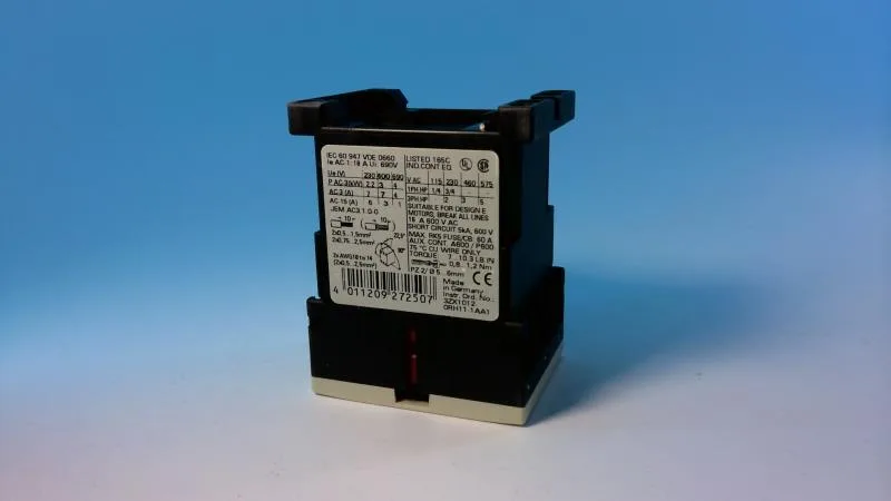
Siemens 3RT1015-1AF01 — Contactors

Siemens 3RT1015-1AF01 SIRIUS Power Contactor, S00, 10 A at 2

MPN3RT1015-1AF01

Siemens SIRIUS power contactor, size S00, order code 3RT1015-1AF01, 3 kW at 400 V AC-2, 10 A at 24 V, screw terminals, IP20.

Source DocumentedChannel stated on listing & quote
Condition PhotosReal unit photos / video on request
WhatsApp AnswersFast human replies for machine-down parts
Worldwide DispatchDHL/FedEx — transit quoted per order
Independent China distributor & sourcing agent· Listing updated Sep 2026

Specifications

3RT1015-1AF01 — Identification
ParameterValue
Contactor frame sizeS00
3RT1015-1AF01 — Ratings & Performance
ParameterValue
Rated operational current, AC-12, max.10 A
Rated operational current, AC-4 @ 400 V6.5 A
Rated value @ 400 V3 A
Rated value @ 500 V3.5 kW
Rated value @ 690 V4 kW
Rated value @ 230 V6 A
Rated value @ 24 V10 A
Rated value @ 60 V2 A
Rated value @ 110 V1 A
Rated value @ 220 V0.3 A
3RT1015-1AF01 — Control & Coil
ParameterValue
Control supply voltage typeAC
Rated value @ 50 Hz0.8 ... 1.1
Rated value @ 50 Hz110 V
3RT1015-1AF01 — Contacts & Poles
ParameterValue
Main poles3
Main NO contacts3
Auxiliary contact reliability1 faulty switching per 100 million (17 V, 1 mA)
3RT1015-1AF01 — Protection & Coordination
ParameterValue
Short-circuit coordination type 1, fusefuse gL/gG: 35 A
Short-circuit coordination type 2, fusefuse gL/gG: 20 A
Aux. switch short-circuit protection, fusefuse gL/gG: 10 A
3RT1015-1AF01 — Connection & Mounting
ParameterValue
Main circuit connectionscrew-type terminals
Aux. / control circuit connectionscrew-type terminals
Conductor cross-section, solid2x (0.5 ... 1.5 mm²), 2x (0.75 ... 2.5 mm²), max. 2x (0.75 ... 4 mm²)
Conductor cross-section, solid or stranded2x (0,5 ... 1,5 mm²), 2x (0,75 ... 2,5 mm²), max. 2x (0,75 ... 4 mm²)
Conductor cross-section, finely stranded w/ ferrule2x (0.5 ... 1.5 mm²), 2x (0.75 ... 2.5 mm²)
Mounting methodscrew and snap-on mounting onto 35 mm standard mounting rail according to DIN EN 50022
Side-by-side mountingYes
3RT1015-1AF01 — Durability
ParameterValue
Durability (operating cycles, typ.)30 000 000
Durability with aux. switch block (cycles, typ.)10 000 000
3RT1015-1AF01 — Environmental
ParameterValue
Operating temperature range-25 ... +60 °C
Installation altitude, max.2 000 m
3RT1015-1AF01 — Mechanical
ParameterValue
Width45 mm
Height57.5 mm
Depth72 mm

Product details

It is rated for 3 kW at 400 V in AC-2 duty (slip-ring motor starting) and 6.5 A at 400 V in AC-4 duty (plugging/inching). At 690 V it handles 4 kW, and at 24 V the rated operational current is 10 A. It occupies 45 mm of DIN rail width, with a height of 57.5 mm and depth of 72 mm.

For general resistive loads (AC-1), the 24 V rating of 10 A gives a baseline, though the actual AC-1 current will be higher at line voltage. The IP20 rating on the front and terminals means it is touch-safe but not sealed against dust ingress — it belongs inside an enclosure.

Main and auxiliary circuits use screw-type terminals. Wire capacity for the main contacts accepts 2x solid conductors from 0.5 to 1.5 mm², 2x from 0.75 to 2.5 mm², or a single conductor up to 4 mm². AWG equivalents are 2x 20–16, 2x 18–14, or 1x 12 AWG. The auxiliary contacts accept the same wire sizes. For Type 1 coordination (contactor may need replacement after a fault), the fuse can be 35 A gL/gG.

Frequently asked questions

What is the closest functional alternative to 3RT1015-1AF01?

The 3RT1017-1AP01 is a higher-rated sibling in the same S00 frame size. It will drop into the same DIN rail footprint and terminal pattern without panel rework, but check your load current — the 3RT1015-1AF01 is the lower-rated unit at 10 A at 24 V versus the 3RT1017-1AP01's higher rating. If your BOM calls for the 3RT1015-1AF01, the 3RT1017-1AP01 is a functional upward substitute only if the higher rating is acceptable for the circuit.

What are the physical dimensions of the 3RT1015-1AF01?

Width is 45 mm, height is 57.5 mm, and depth is 72 mm. It mounts on a 35 mm DIN rail per EN 50022.

What wire sizes does the 3RT1015-1AF01 accept?

Main and auxiliary screw terminals accept 2x solid conductors from 0.5 to 1.5 mm², 2x from 0.75 to 2.5 mm², or a single conductor up to 4 mm². AWG equivalents are 2x 20–16, 2x 18–14, or 1x 12 AWG.

What compliance documentation is available for the 3RT1015-1AF01?

The part carries a substance prohibition date of 01.07.2006, indicating RoHS compliance. It is designed to IEC 60947 standards and carries the IEC 81346-2 reference code Q for switching devices. Specific UL/CSA file numbers are not in the provided record, but as a Siemens SIRIUS product it typically carries UL and CSA certifications — verify the specific listing for your jurisdiction.

MPN
3RT1015-1AF01