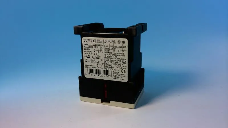
It mounts via screw or snap-on onto a 35 mm DIN rail per EN 50022, with a 45 mm width that occupies three standard 17.5 mm modular pitches. The contactor is rated for AC-3 duty at 7 A at 400 V, delivering 3 kW at 400 V and 4 kW at 690 V — suitable for small induction motors on pumps, fans, and conveyors.
The AC-4 rating of 6.5 A at 400 V is the one to watch if the contactor sees inrush from reversing or plugging — it's lower than the AC-3 figure, so a motor that starts fine may exceed the contactor's capability during a reversing cycle. Auxiliary contact ratings are given for DC switching: 10 A at 24 V, 2 A at 60 V, 1 A at 110 V, and 0.3 A at 220 V. These are the DC-13 values for inductive loads like relay coils; the 24 V rating is the one most often used for PLC-level control signals. This matters for selectivity studies in a panel — if upstream protection is set above 35 A, the contactor itself becomes the weakest link. This is the standard for most control panels without sealed enclosures. Electrical life will be shorter and depends on the switching current and duty cycle.
Physical integration and wiring
The depth includes the coil terminals and main contact terminals, so verify clearance to the enclosure door or gland plate. Screw terminals on the main circuit accept 2x (0.5 to 1.5 mm²), 2x (0.75 to 2.5 mm²), or up to 2x (0.75 to 4 mm²) solid or stranded conductors. AWG equivalents are 2x (20 to 16), 2x (18 to 14), and 1x 12. The terminal design allows two conductors per clamp, which simplifies daisy-chaining in a motor starter group. Front protection is IP20, meaning finger-safe from the front but not protected against water ingress. The terminal area is also IP20. This is standard for panel-mounted components — the enclosure provides the overall IP rating.
Environmental limits
Coil operating range is 0.8 to 1.1 times rated voltage at 50 Hz and 0.85 to 1.1 at 60 Hz — the wider 50 Hz tolerance accommodates brownout conditions common in industrial power systems.