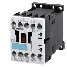
SIRIUS S00 power contactor, 10 A AC-12, screw terminals
The Siemens 3RT1015-1AP02-1AA0 is a SIRIUS-branded power contactor in the compact S00 frame size, rated for a maximum operating current of 10 A in AC-12 duty (resistive loads) and capable of switching motor loads up to 4 kW at 690 V in AC-3. The AC-12 rating of 10 A is the headline figure for resistive load switching — think heater banks or lighting contactor service. For motor duty, the AC-3 rating at 690 V (4 kW) is the one that governs the real-world fit; the AC-4 rating at 400 V (6.5 A) covers reversing or inching applications where the contactor makes and breaks stalled-rotor current.
For a BOM freeze or long-term planning, this part is specified into the design without an imminent replacement risk. If you are maintaining a panel that was originally built around the larger-frame 3RT1016-1AG61, note that the S00 frame shares the same DIN-rail footprint and terminal pitch — the swap is mechanical, not electrical; the 3RT1015 carries lower current ratings, so verify the load before substituting.
Main circuit terminals accept solid or stranded conductors: 2x (0.5 to 1.5 mm²), 2x (0.75 to 2.5 mm²), and a maximum of 2x (0.75 to 4 mm²). AWG equivalents are 2x (20 to 16), 2x (18 to 14), and 1x 12. The screw-type termination is field-serviceable with a standard Pozidriv or flat-blade driver — no special crimp tool needed.
Coil and auxiliary contact configuration
The coil is rated for 230 V at 50 Hz and 230 V at 60 Hz, with an operating range of 0.8 to 1.1 times rated voltage at 50 Hz and 0.85 to 1.1 at 60 Hz. That means at 50 Hz the coil holds in down to 184 V and picks up reliably at 253 V; at 60 Hz the dropout margin is slightly tighter. No built-in auxiliary contacts are present — the instantaneous contact count is zero, so any feedback or status signaling requires an add-on auxiliary contact block. Auxiliary contact current ratings by voltage: 10 A at 24 V, 2 A at 60 V, 1 A at 110 V, 0.3 A at 220 V, 6 A at 230 V, and 3 A at 400 V. These are the switching capacities for the auxiliary contacts if an add-on block is fitted — useful when selecting a block for a 24 VDC PLC input or a 230 VAC pilot light.
Short-circuit coordination and environmental limits
For Type 2 coordination (contactor remains operational after a fault), the fuse is gL/gG 20 A.