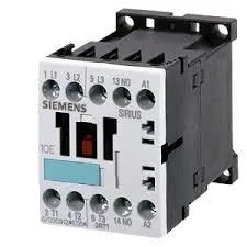
It mounts via screw or snap-on onto 35 mm DIN rail per DIN EN 50022, fitting into standard control panels with 45 mm width and 57.5 mm height. The front and terminal faces carry IP20 finger-safe protection, so it can be installed in open panels without additional shrouding.
Motor ratings and duty cycles
For motor switching, the contactor is rated 3 kW at AC-2 duty on 400 V (standard squirrel-cage start/run), and 6.5 A at AC-4 duty on 400 V (plugging/inching). At 690 V it handles 4 kW, and at 500 V, 3.5 kW. These figures define the real load capacity — not the 10 A AC-12 resistive rating, which applies to non-inductive loads only.
The 24 VDC coil operates across a voltage tolerance of 0.8 to 1.1 times rated at 50 Hz, and 0.85 to 1.1 at 60 Hz. That means it picks up reliably at about 19.2 VDC and holds in up to 26.4 VDC. The coil draws no continuous power figure listed here, but the auxiliary contact ratings give the switching capacity: 10 A at 24 VDC, 2 A at 60 VDC, 1 A at 110 VDC, and 0.3 A at 220 VDC.
Mounts side-by-side with no gap required — the 6 mm clearance is to adjacent metalwork or enclosure walls, not between contactors. Screw terminals accept 2x (0.5 to 1.5 mm²) solid/stranded, 2x (0.75 to 2.5 mm²), or max 2x (0.75 to 4 mm²). AWG equivalents are 2x (20 to 16), 2x (18 to 14), and 1x 12.
Short-circuit protection and coordination
These are the factory-recommended values for the main circuit.