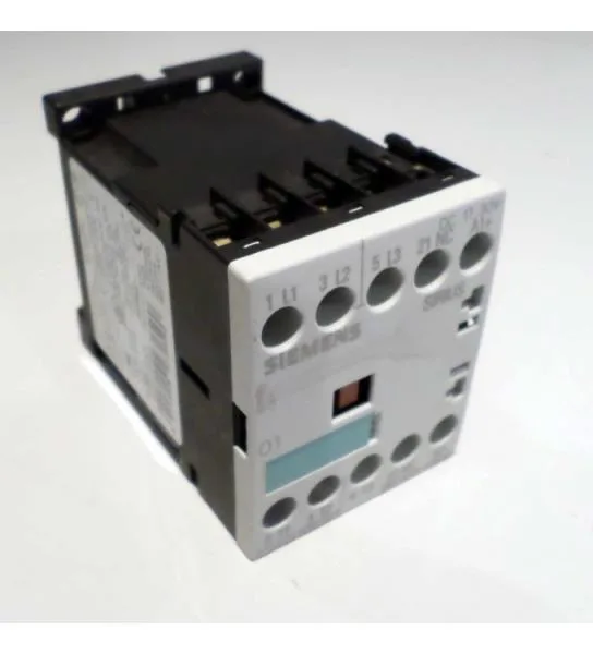
Auxiliary contact ratings are specified across voltages: 10 A at 24 V, 6 A at 230 V, 3 A at 400 V, and 0.3 A at 220 V DC. These values govern the switching capacity for control circuits, pilot lights, or PLC inputs connected through the auxiliary contacts. Short-circuit protection coordination is defined: Type 2 coordination requires a gL/gG fuse rated 20 A, while Type 1 coordination allows a 35 A fuse. This lets the panel designer select the upstream protection based on whether they need the contactor to remain serviceable after a fault (Type 2) or are willing to replace it (Type 1).
The contactor measures 57.5 mm high and 72 mm deep, fitting within the S00 envelope. Terminals are IP20 finger-safe on the front and at the connection points. Screw terminals accept solid or stranded conductors: 2x (0.5 to 1.5 mm²), 2x (0.75 to 2.5 mm²), or up to 2x (0.75 to 4 mm²) per clamp. AWG equivalents are 2x (20 to 16), 2x (18 to 14), or 1x 12.