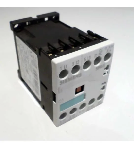
Siemens 3RT1015-2JB41 — Contactors

Siemens 3RT1015-2JB41 SIRIUS S00 power contactor, 24 VDC, sp

MPN3RT1015-2JB41

Siemens SIRIUS 3RT1015-2JB41 power contactor, size S00, 24 VDC coil with integrated diode suppression, spring-loaded terminals for main and auxiliary circuits, IP20 front and terminal protection.

Source DocumentedChannel stated on listing & quote
Condition PhotosReal unit photos / video on request
WhatsApp AnswersFast human replies for machine-down parts
Worldwide DispatchDHL/FedEx — transit quoted per order
Independent China distributor & sourcing agent· Listing updated Sep 2026

Specifications

3RT1015-2JB41 — Identification
ParameterValue
Contactor frame sizeS00
3RT1015-2JB41 — Ratings & Performance
ParameterValue
Rated operational current, AC-12, max.10 A
Rated operational current, AC-4 @ 400 V6.5 A
Rated value @ 400 V3 A
Rated value @ 500 V3.5 kW
Rated value @ 690 V4 kW
Rated value @ 230 V6 A
Rated value @ 24 V10 A
Rated value @ 60 V2 A
Rated value @ 110 V1 A
Rated value @ 220 V0.3 A
3RT1015-2JB41 — Control & Coil
ParameterValue
Control supply voltage typeDC
3RT1015-2JB41 — Contacts & Poles
ParameterValue
Main poles3
Main NO contacts3
Auxiliary contact reliability1 faulty switching per 100 million (17 V, 1 mA)
3RT1015-2JB41 — Protection & Coordination
ParameterValue
Short-circuit coordination type 1, fusefuse gL/gG: 35 A
Short-circuit coordination type 2, fusefuse gL/gG: 20 A
Aux. switch short-circuit protection, fusefuse gL/gG: 10 A
3RT1015-2JB41 — Connection & Mounting
ParameterValue
Main circuit connectionspring-loaded terminals
Aux. / control circuit connectionspring-loaded terminals
Conductor cross-section, solid2x (0.25 ... 2.5 mm²)
Conductor cross-section, solid or stranded2x (0,25 ... 2,5 mm²)
Conductor cross-section, finely stranded w/ ferrule2x (0.25 ... 1.5 mm²)
Mounting methodscrew and snap-on mounting onto 35 mm standard mounting rail according to DIN EN 50022
Side-by-side mountingYes
3RT1015-2JB41 — Durability
ParameterValue
Durability (operating cycles, typ.)30 000 000
3RT1015-2JB41 — Environmental
ParameterValue
Operating temperature range-25 ... +60 °C
Installation altitude, max.2 000 m
3RT1015-2JB41 — Mechanical
ParameterValue
Width45 mm
Height60 mm
Depth73 mm

Product details

It switches motor loads up to 3 kW in AC-2 duty at 400 V and handles 6.5 A in AC-4 reversing or plugging service at the same voltage. The main and auxiliary circuits terminate through spring-loaded terminals, accepting 2x (0.25... 2.5 mm²) solid or stranded wire or 2x (24... 14 AWG). Side-by-side mounting is permitted, which means the 45 mm width per pole stacks cleanly in a multi-contactor group without forced spacing. The enclosure carries IP20 on the front and at the terminals, suitable for enclosed panel environments where no washdown or dust ingress protection is needed.

The integrated diode suppresses the inductive kickback on coil de-energization, which protects nearby electronics and simplifies panel wiring — no external flyback diode needed across the coil terminals. These are the ratings that govern real motor life, not the thermal current alone. Type 1 and Type 2 coordination fuse requirements are specified: 35 A gL/gG for Type 1, 20 A gL/gG for Type 2. This means the contactor withstands fault current up to those fuse let-through levels without welding or fire risk, which is critical for meeting IEC 60947-4-1 short-circuit coordination in a panel schedule.

Where this class of part is used

Power contactors of this size (S00) are the standard building block for controlling three-phase motors up to about 4 kW, resistive heating loads, and capacitor banks in industrial control panels. The 3RT1015-2JB41 fits into motor control centers, conveyor drives, pump panels, and HVAC equipment where a 24 VDC control voltage is already available from a PLC or safety relay.

For compliance documentation, the part carries a substance prohibitance date of 01.07.2006, aligning with RoHS and REACH substance restrictions. The IEC 81346-2 reference code Q confirms its function as a switching device for power circuits, which is relevant for panel documentation and traceability audits.

Frequently asked questions

What is the closest functional alternative to the 3RT1015-2JB41?

The 3RT1015-1BB42 is the closest sibling within the same SIRIUS S00 frame size. The key difference is termination: the -2JB41 uses spring-loaded terminals, while the -1BB42 uses screw terminals. Both share the same 24 VDC coil, same motor ratings, and same DIN-rail footprint, so a panel designed for one can accept the other without rewiring the rail position — only the wire termination method changes.

What wire sizes does the spring terminal accept?

The spring-loaded terminals accept 2x (0.25... 2.5 mm²) solid or stranded conductors, or 2x (24... 14 AWG). This covers most control and small power wiring used in panel builds.

Will the 3RT1015-2JB41 drop into a panel specified around the 3RT1015-1BB42?

Yes, the two parts share the same S00 frame size, same mounting footprint on 35 mm DIN rail, and same 24 VDC coil. The only difference is the termination type — spring vs. screw. No rewiring of the rail or control circuit is needed; the wire preparation method (ferrule vs. bare wire) may change.

What compliance documentation is available for the 3RT1015-2JB41?

The part carries a RoHS substance prohibitance date of 01.07.2006, indicating compliance with RoHS and REACH substance restrictions. The IEC 81346-2 reference code Q is assigned for panel documentation and traceability.

MPN
3RT1015-2JB41