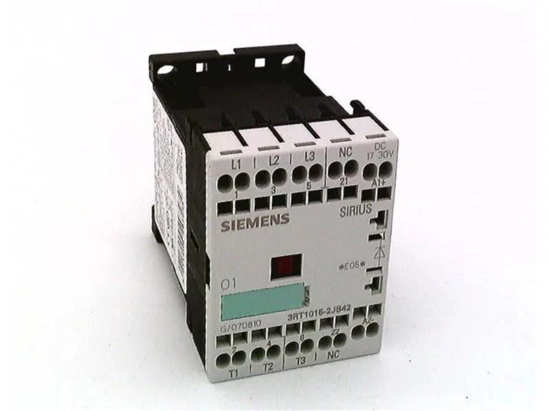
Siemens 3RT1015-2JB42 — Contactors

Siemens SIRIUS 3RT1015-2JB42 Power Contactor, Size S00, 24 V

MPN3RT1015-2JB42

Siemens SIRIUS 3RT1015-2JB42 power contactor, size S00, 24 VDC coil with integrated diode suppression, spring-loaded terminals, 45 mm width, screw and snap-on DIN rail mounting.

$244.64Ref. price · indicative, final on quote
Source DocumentedChannel stated on listing & quote
Condition PhotosReal unit photos / video on request
WhatsApp AnswersFast human replies for machine-down parts
Worldwide DispatchDHL/FedEx — transit quoted per order
Independent China distributor & sourcing agent· Listing updated Sep 2026

Specifications

3RT1015-2JB42 — Identification
ParameterValue
Contactor frame sizeS00
3RT1015-2JB42 — Ratings & Performance
ParameterValue
Rated operational current, AC-4 @ 400 V6.5 A
Rated value @ 400 V3 A
Rated value @ 500 V3.5 kW
Rated value @ 690 V4 kW
Rated value @ 230 V6 A
Rated value @ 24 V10 A
Rated value @ 60 V2 A
Rated value @ 110 V1 A
Rated value @ 220 V0.3 A
3RT1015-2JB42 — Control & Coil
ParameterValue
Control supply voltage typeDC
3RT1015-2JB42 — Contacts & Poles
ParameterValue
Main poles3
Main NO contacts3
Auxiliary contact reliability1 faulty switching per 100 million (17 V, 1 mA)
3RT1015-2JB42 — Protection & Coordination
ParameterValue
Short-circuit coordination type 1, fusefuse gL/gG: 35 A
Short-circuit coordination type 2, fusefuse gL/gG: 20 A
Aux. switch short-circuit protection, fusefuse gL/gG: 10 A
3RT1015-2JB42 — Connection & Mounting
ParameterValue
Main circuit connectionspring-loaded terminals
Conductor cross-section, solid2x (0.25 ... 2.5 mm²)
Conductor cross-section, finely stranded w/ ferrule2x (0.25 ... 1.5 mm²)
Side-by-side mountingYes
3RT1015-2JB42 — Durability
ParameterValue
Durability (operating cycles, typ.)30 000 000
3RT1015-2JB42 — Environmental
ParameterValue
Operating temperature range-25 ... +60 °C
3RT1015-2JB42 — Mechanical
ParameterValue
Width45 mm
Height60 mm
Depth73 mm

Product details

At 45 mm wide and 73 mm deep, it fits standard DIN-rail enclosures with typical gland-plate clearance. The spring-loaded terminals on the main current circuit accept 2x (0.25... 2.5 mm²) solid or stranded conductors, or 2x (24... 14) AWG, so no ferrule crimping is required for solid wire — a time saver during panel build. The IP20 finger-safe enclosure on the front and terminals means it can be installed in a standard IP54 or higher cabinet without additional shrouding for the contactor body itself.

The magnet coil is rated for 24 V DC and includes an integrated surge suppressor designed as a diode. Closing power is 2.3 W; holding power is also 2.3 W — a continuous-duty coil that stays cool at full rated voltage. The diode polarity must be observed: if the control circuit is driven by a PLC output or relay, verify the free-wheel diode orientation before energizing inductive loads downstream. Switching capacity at 24 V rated value is 10 A, dropping to 2 A at 60 V, 1 A at 110 V, and 0.3 A at 220 V — these are the DC-13 / resistive load curves for the auxiliary contacts. For the main poles, AC-12 maximum operating current is 10 A.

Load switching and coordination

For motor loads, the contactor is rated at AC-2 3 kW at 400 V and AC-4 6.5 A at 400 V. At 400 V AC-3 duty it switches 3 A, and at 690 V AC-3 it handles 4 kW. Type 2 coordination requires a 20 A gL/gG fuse; Type 1 coordination allows a 35 A gL/gG fuse.

For a line-down replacement or a new panel build, confirm the coil voltage (24 V DC) and the spring-loaded terminal preference match your BOM — the -2JB42 suffix encodes both the DC coil and the spring-clamp main terminals.

Frequently asked questions

What is the closest functional alternative — 3RT1015-1BB42?

The 3RT1015-1BB42 is the screw-terminal variant of the same size S00 contactor with a 24 V DC coil but without the integrated diode suppression. The -2JB42 uses spring-loaded terminals and includes the diode. If your panel is wired for screw terminals and you supply external flyback suppression, the -1BB42 drops into the same footprint and DIN rail slot without rewiring the load side.

What is the depth of 3RT1015-2JB42?

The depth is 73 mm, with a width of 45 mm and height of 60 mm.

What wire sizes do the spring-loaded terminals accept?

The spring-loaded terminals on the main current circuit accept 2x (0.25... 2.5 mm²) solid or stranded conductors, or 2x (24... 14) AWG.

Will 3RT1015-2JB42 drop into a panel specified for 3RT1015-1BB42 without rewiring?

Yes, the physical footprint (size S00, 45 mm width, DIN rail snap-on) is identical. The difference is terminal type: the -2JB42 uses spring-loaded terminals, while the -1BB42 uses screw terminals. If the panel already has ring or fork terminals crimped for screw clamps, you may need to change to ferruled or bare wire for the spring cage.

MPN
3RT1015-2JB42