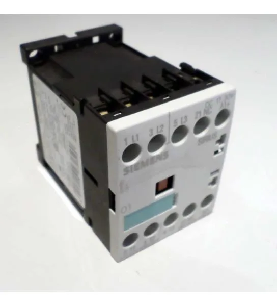
It carries a 24 VDC coil with an integrated diode surge suppressor, and the main circuit connects via spring-loaded terminals — no screw torque to verify, just strip and push.
Rated operational current is 10 A at 24 V, but the real motor-switching number is the AC-3 rating: 3.5 kW at 500 V and 4 kW at 690 V. That's the figure that tells you whether this contactor handles your 5.5 HP motor at 480 V — it does, with headroom. For resistive loads (AC-1), the maximum operating current is 10 A. The coil pulls 1.4 W to close and holds at 1.4 W DC — that's a low continuous drain for a PLC output or a 24 VDC power supply. The integrated diode means you don't need an external flyback diode across the coil, but verify polarity: reverse voltage kills the diode and the coil driver.
Spring-loaded terminals accept 2x (0.25 to 2.5 mm²) solid or stranded, or 2x (24 to 14 AWG). Strip length is standard for spring clamps — about 8 to 10 mm. No screwdriver needed for the power connections, which saves time on repetitive wiring. For Type 2 coordination (contactor remains fully functional after a fault), use a 20 A gL/gG fuse. That's the spec for sizing your branch circuit protection.
The 3RT1015-2VB42 is a specific variant: S00 frame, 24 VDC coil with diode, spring terminals. If your panel was built around a screw-terminal version (like the 3RT1015-1BB42), the spring-terminal variant drops into the same footprint and same DIN rail slot — just different wiring method. If your existing panel uses a 3RT1016-2AP02 (larger frame or different coil voltage), the physical size and terminal layout differ; verify the mounting hole pattern and coil voltage before swapping.