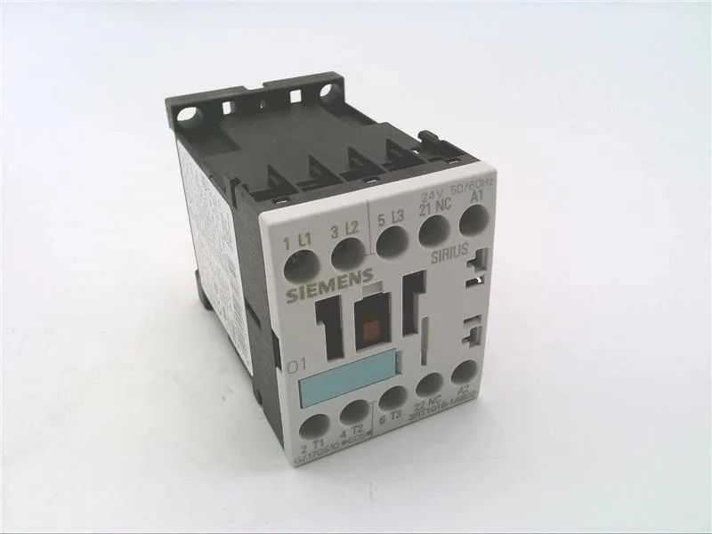
The 3RT1016-1AB02-1AA0: The AC-4 rating of 8.5 A at 400 V governs inching and plugging duty — the load that sees the highest contact wear. If your application cycles the motor under load, that's the number that decides contact life, not the AC-3 figure.
Wiring and terminal capacity
Screw-type terminals on the main circuit accept 2x (0.5 to 1.5 mm²), 2x (0.75 to 2.5 mm²), or max 2x (0.75 to 4 mm²) solid or stranded. AWG equivalents: 2x (20 to 16), 2x (18 to 14), 1x 12. That covers the common panel-building wire sizes for a contactor this frame. Side-by-side mounting is permitted with zero clearance — no derating required for adjacent contactors at the same ambient. The 6 mm spacing figure refers to the clearance to grounded metalwork, not between units.
This is the spec the panel designer needs to match the SCCR label. The IP20 front and terminal protection is adequate for enclosed installation.
Auxiliary contact ratings and mechanical life
The built-in auxiliary contacts are rated 10 A at 24 V, 2 A at 60 V, 1 A at 110 V, and 0.3 A at 220 V — all AC-12 or AC-15 duty. That's the coil and armature, not the contacts — electrical life will be lower and depends on the switched current and duty cycle.
Environmental limits
Maximum altitude 2000 m without derating. The coil hold range is 0.8 to 1.1 x Us at 50 Hz, 0.85 to 1.1 x Us at 60 Hz — so at 24 V nominal, dropout is around 19.2 V at 50 Hz, 20.4 V at 60 Hz.