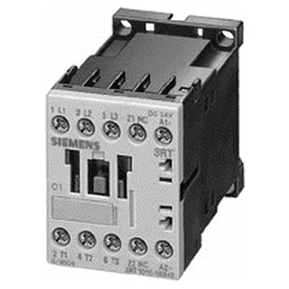
Siemens 3RT1016-1AL05 — Contactors

Siemens 3RT1016-1AL05 SIRIUS Power Contactor, S00 Frame, 24

MPN3RT1016-1AL05

Siemens SIRIUS power contactor, size S00, 3-pole, 24 VDC coil, screw terminals, 5.5 kW at 690 V, IP20 front.

Source DocumentedChannel stated on listing & quote
Condition PhotosReal unit photos / video on request
WhatsApp AnswersFast human replies for machine-down parts
Worldwide DispatchDHL/FedEx — transit quoted per order
Independent China distributor & sourcing agent· Listing updated Sep 2026

Specifications

3RT1016-1AL05 — Identification
ParameterValue
Contactor frame sizeS00
3RT1016-1AL05 — Ratings & Performance
ParameterValue
Rated operational current, AC-4 @ 400 V8.5 A
Rated value @ 400 V3 A
Rated value @ 500 V4.5 kW
Rated value @ 690 V5.5 kW
Rated value @ 230 V6 A
Rated value @ 24 V10 A
Rated value @ 60 V2 A
Rated value @ 110 V1 A
Rated value @ 220 V0.3 A
3RT1016-1AL05 — Control & Coil
ParameterValue
Control supply voltage typeAC
Rated value @ 50 Hz0.8 ... 1.1
Rated value @ 50 Hz125 V
3RT1016-1AL05 — Contacts & Poles
ParameterValue
Main poles3
Main NO contacts3
Auxiliary contact reliability1 faulty switching per 100 million (17 V, 1 mA)
3RT1016-1AL05 — Protection & Coordination
ParameterValue
Short-circuit coordination type 1, fusefuse gL/gG: 35 A
Short-circuit coordination type 2, fusefuse gL/gG: 20 A
Aux. switch short-circuit protection, fusefuse gL/gG: 10 A
3RT1016-1AL05 — Connection & Mounting
ParameterValue
Main circuit connectionscrew-type terminals
Conductor cross-section, solid2x (0.5 ... 1.5 mm²), 2x (0.75 ... 2.5 mm²), max. 2x (0.75 ... 4 mm²)
Conductor cross-section, finely stranded w/ ferrule2x (0.5 ... 1.5 mm²), 2x (0.75 ... 2.5 mm²)
Side-by-side mountingYes
3RT1016-1AL05 — Durability
ParameterValue
Durability (operating cycles, typ.)30 000 000
Durability with aux. switch block (cycles, typ.)10 000 000
3RT1016-1AL05 — Environmental
ParameterValue
Operating temperature range-25 ... +60 °C
3RT1016-1AL05 — Mechanical
ParameterValue
Width45 mm
Height57.5 mm
Depth114 mm

Product details

It carries three main poles rated for AC-3 duty at 5.5 kW at 690 V and 4.5 kW at 500 V, with a 24 VDC coil that pulls in reliably across the 0.8 to 1.1 times rated voltage range at 50 Hz and 0.85 to 1.1 at 60 Hz. The S00 frame means this contactor occupies 45 mm width on a DIN rail, with a depth of 114 mm and height of 57.5 mm — tight enough for dense panel layouts where every millimeter of rail space counts.

The 5.5 kW rating at 690 V is the AC-3 motor switching capability — that's the real-world number for sizing this contactor to a three-phase induction motor. At 400 V, the AC-3 rating drops to 3 A (about 1.5 kW), so don't assume the 690 V figure scales linearly; the contactor's thermal current rating and the duty cycle govern the actual load it can handle continuously. The mechanical life of 30 million operations is typical for a contactor this size, but the electrical life will be shorter under full-load switching — expect around 1 to 2 million operations at rated AC-3 current, depending on the switching frequency and the inrush current of the motor. The screw terminals accept wire from 0.5 to 4 mm² (solid or stranded), with AWG equivalents from 20 to 12. That covers most control wiring and small power feeds, but if you're running 6 mm² or larger, you'll need to step up to the next frame size. The IP20 rating on the front and terminals means it's finger-safe for panel installation — no special cover needed inside a locked enclosure. The 6 mm side clearance requirement is for heat dissipation when mounting multiple contactors side-by-side; if you pack them tight, derate the continuous current per the manufacturer's table. The operating temperature range of -25 to +60 °C covers most indoor industrial conditions, but above 40 °C you'll need to derate the continuous current — the coil hold-in voltage also shifts with temperature, so verify the control voltage stays within the 0.8 to 1.1 range at the panel's ambient temperature.

Side-by-side mounting is allowed, but maintain the 6 mm gap between contactors for airflow unless you're derating. The screw terminals are the standard for the main circuit; auxiliary contact blocks (like the 3RT1916 series) snap onto the front or side without additional wiring. The coil terminals are also screw type, so you'll need a small flathead or Pozidriv for termination. For type 2 coordination (contactor remains usable after a fault), use a 20 A gL/gG fuse. This is critical for panel builders specifying the correct branch circuit protection.

Frequently asked questions

What is the closest functional alternative to the 3RT1016-1AL05?

The 3RT1016-2AP02 is a sibling in the same S00 frame size, but it uses a 24 VAC/DC coil with different coil termination (spring-cage terminals on the coil side). The 3RT1023-1AL20 is a larger S0 frame contactor with higher current ratings. If you need the same 24 VDC coil and screw terminals, the 3RT1016-1AL05 is the direct fit; the 3RT1016-2AP02 would require verifying the coil circuit wiring and terminal compatibility.

What are the key dimensions for panel layout?

Width is 45 mm, height is 57.5 mm, depth is 114 mm. It mounts on 35 mm DIN rail per EN 50022. Side clearance of 6 mm is required between contactors for heat dissipation unless derating is applied.

What wire sizes does the 3RT1016-1AL05 accept?

The screw terminals accept 2x (0.5 to 1.5 mm²), 2x (0.75 to 2.5 mm²), and max 2x (0.75 to 4 mm²) solid or stranded. AWG equivalents are 2x (20 to 16), 2x (18 to 14), and 1x 12.

Will the 3RT1016-1AL05 drop into a panel designed for the 3RT1016-2AP02?

Mechanically yes — same S00 frame, same DIN rail footprint, same 45 mm width. The difference is the coil termination: the 1AL05 uses screw terminals for the coil, while the 2AP02 uses spring-cage terminals. If the panel wiring was terminated for spring-cage, you may need to re-terminate or use ferrule pins for the screw clamp. The main power terminals are screw type on both variants.

MPN
3RT1016-1AL05