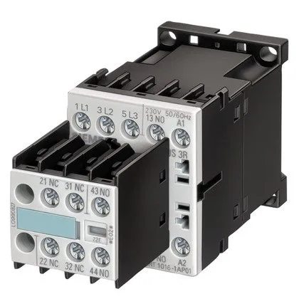
Coil and switching ratings
The 3RT1016-1BB42: The DC coil draws 3.3 W during both closing and holding, so the control transformer or power supply must be sized for continuous 3.3 W draw per contactor. The coil pickup is rated at 0.85 x rated voltage (20.4 VDC minimum) and dropout at 1.1 x rated voltage (26.4 VDC) — ensure the control supply stays within this band for reliable operation. Switching capacity varies by duty: at AC-2 (400 V) the contactor is rated for 4 kW motor load; at AC-4 (400 V) the operational current is 8.5 A for reversing or inching duty. The maximum operational current in AC-12 (resistive) is 10 A. For DC switching, the contactor is rated at 24 V / 10 A, 60 V / 2 A, 110 V / 1 A, 220 V / 0.3 A, and 230 V / 6 A — the DC ratings drop sharply above 60 V, so verify the load type before specifying for DC circuits. Motor power ratings at AC-3 duty: 4.5 kW at 500 V, 5.5 kW at 690 V. For a 400 V line, the AC-3 rating is typically around 4 kW (derived from the 8.5 A AC-4 figure — AC-3 is usually higher). The contactor is also rated for 3 A at 400 V in unspecified duty, likely resistive or light inductive.
The S00 frame occupies 45 mm width, 57.5 mm height, 72 mm depth — fits standard 45 mm-wide DIN-rail slots. Side-by-side mounting is permitted, so multiple contactors can be ganged without spacing. Main and auxiliary/control circuits use screw-type terminals. Wire capacity: solid or stranded 2x (0.5…1.5 mm²), 2x (0.75…2.5 mm²), max 2x (0.75…4 mm²) for main contacts; auxiliary contacts accept 2x (20…16 AWG), 2x (18…14 AWG), 1x 12 AWG. Strip length is not specified but standard for screw terminals is 8–10 mm. Degree of pollution 3 (industrial environment with conductive pollution).
Protection and coordination
The contactor's own short-circuit withstand is not separately listed, but these fuse recommendations define the upstream protection. The mechanical life is typical 30 million operations — this is the no-load mechanical endurance; electrical life depends on switching current and voltage.
RoHS compliance date is 01.07.2006, indicating the design meets the original RoHS directive. No UL or CSA listing is explicitly in the evidence, but the product is designed to IEC standards typical for European panels.